You are using an out of date browser. It may not display this or other websites correctly.
You should upgrade or use an alternative browser.
You should upgrade or use an alternative browser.
NASA ACES suit disconnects
- Thread starter antarusfree
- Start date
-
- Tags
- aces disconnects nasa replica suit
antarusfree
Well-Known Member
1/32" (0.8255 mm) radii is called out for all corners of the clamp ring. This is likely standard on other exterior corners as well.
 the biggest one I used is 0,6mm. Can try to use 0,8, but that's the biggest one.
I don't think, that 0,8 mm is the minimum radius on these disconnects, but I can be wrong.
I think that this radius is used on the raised areas.
This is why I have been saying the radii look too small. I've owned and handled a great many real parts, and grew up around an aerospace machine shop. The print I have is an original print for this same part, but for an EMU ring. (I made an error on the conversion, the actual mm is .79375, so .8mm) I would assume this to be the minimum on all exposed corners.
antarusfree
Well-Known Member
This is why I have been saying the radii look too small. I've owned and handled a great many real parts, and grew up around an aerospace machine shop. The print I have is an original print for this same part, but for an EMU ring. (I made an error on the conversion, the actual mm is .79375, so .8mm) I would assume this to be the minimum on all exposed corners.
EMU uses Apollo era disconnects, am I correct?
antarusfree
Well-Known Member
Checking those radii again and again.
The raised areas are now 0,8mm but the rest is mostly 0,5mm.
These tab spring are still mystery...


The raised areas are now 0,8mm but the rest is mostly 0,5mm.
These tab spring are still mystery...
I have been thinking of how to make this work, and why there is a hole in the top of the lock tab.
Potroclo suggested a extension spring, but I could not see how you would assemble it with the dovetailed lock tab and put the spring in tension.
However, while this design I've come up with does not feel right, it is a way to make this system work with this type of spring and the current configuration. (NOTE: I do not have correct proportions or dimensions on this drawing.)
The threaded pin is partially threaded in, then the lock tab is slid past it's "lock" position so the nose of the threaded pin aligns with the loop on the extension spring. The lock tab is then pulled back and the threaded pin is screwed further down until the nose descends into the 2nd, smaller groove. This then puts the extension spring in tension, and gives a positive stop point for the lock tab.
antarusfree
Well-Known Member
I have been thinking of how to make this work, and why there is a hole in the top of the lock tab.
Potroclo suggested a extension spring, but I could not see how you would assemble it with the dovetailed lock tab and put the spring in tension.
However, while this design I've come up with does not feel right, it is a way to make this system work with this type of spring and the current configuration. (NOTE: I do not have correct proportions or dimensions on this drawing.)
The threaded pin is partially threaded in, then the lock tab is slid past it's "lock" position so the nose of the threaded pin aligns with the loop on the extension spring. The lock tab is then pulled back and the threaded pin is screwed further down until the nose descends into the 2nd, smaller groove. This then puts the extension spring in tension, and gives a positive stop point for the lock tab.
View attachment 972980
Interesting idea, but in this case there will be a visible slot for the screw/pin to move the tab up, as you can see here:

Also here are some views of the locking tabs to see, what is in the hole. I don't think it's a screw.


Edit: Actuality, looking at it closer, it will work this way. Your hole is too close to the edge, by about half the diameter of the hole. Also, your slot is not for the full diameter of the hole size, as the bottom diameter of the pin is half of the head (hole) size.
Last edited:
Here is what I referring to.
However, I still don't like it, it does not feel correct. Looking closer at the hole in the tab, you are correct, there does not appear to be a pin in the hole. Knowing the type of safety concerns that arise with astronauts / Pilots and NASA / Air Force, I'm guessing that hole is a contingency for if the lock tab gets jammed and with the use of a tool, the wearer can use that hole to forcibly pull the lock latch back.
I have another Idea I'll sketch up.
Attachments
I'm not sure the dimensions you have for these tabs, so I'm not sure of the actual hardware sizes (But they will be imperial not metric)
However, if things don't get too small to be practical, I think this design would explain no pin in the hole of the tab and the thing you can see in the bottom of the hole, which I think is a spring.
You want any screws you use to be in a position so if they back out, cant fail in a way to lock the item in an unworkable position. While the screw in from the bottom could back out and jam, this may be why there is the hole in the lock tab to force the tab to the unlock position with use of a tool to grab that hole. A second hole would be needed to hold the spring back, so when the allen head cap screw is threaded into the lock tab, the spring will be under compression all the time.
Attachments
antarusfree
Well-Known Member
I'm not sure the dimensions you have for these tabs, so I'm not sure of the actual hardware sizes (But they will be imperial not metric)
However, if things don't get too small to be practical, I think this design would explain no pin in the hole of the tab and the thing you can see in the bottom of the hole, which I think is a spring.
You want any screws you use to be in a position so if they back out, cant fail in a way to lock the item in an unworkable position. While the screw in from the bottom could back out and jam, this may be why there is the hole in the lock tab to force the tab to the unlock position with use of a tool to grab that hole. A second hole would be needed to hold the spring back, so when the allen head cap screw is threaded into the lock tab, the spring will be under compression all the time.
I like this idea a lot. I will try to implement it to the design.
Today I went through about 7000 images from the NASA gallery to find any better views on the locking tabs.
I will need to make some minor changes.
Tomorrow I will also receive 300 stainless bearing balls.
Mad Monkey
Well-Known Member
So interesting following along with thus information
Potroclo
Well-Known Member
That's what I suggested, except I didn't account for the 2nd smaller groove because the tab's movement is limited by the spring's groove itself once assembled and the suit ring that receives the tab once the glove is attached. Also though of a spring pin instead of a threaded screw.I have been thinking of how to make this work, and why there is a hole in the top of the lock tab.
Potroclo suggested a extension spring, but I could not see how you would assemble it with the dovetailed lock tab and put the spring in tension.
However, while this design I've come up with does not feel right, it is a way to make this system work with this type of spring and the current configuration. (NOTE: I do not have correct proportions or dimensions on this drawing.)
The threaded pin is partially threaded in, then the lock tab is slid past it's "lock" position so the nose of the threaded pin aligns with the loop on the extension spring. The lock tab is then pulled back and the threaded pin is screwed further down until the nose descends into the 2nd, smaller groove. This then puts the extension spring in tension, and gives a positive stop point for the lock tab.
View attachment 972980
But anyway, as you said it does not feel right.
Furthermore, I think you are spot on with the idea of the misterious hole being to force the tab to the unlock position with use of a tool to grab that hole. It makes sense not only during assembly, it can also be a feature during regular use of the suit, say if you have to unlock it yourself with both gloves on and the tab grooves or the glove fingers are slippery for any reason...
Your last idea feels really good!
antarusfree
Well-Known Member
Haven't done much today, but I went through more pictures for more reference.
Wanting to finish all part this week, so I can have the first prototype by the next week.
Wanting to finish all part this week, so I can have the first prototype by the next week.
antarusfree
Well-Known Member
Today, I have been editing the whole disconnect design.
Next I will make the grooves for the lock spring.


Imgill: I have been fighting with the radii again. 0,8mm is too much for this.
I am happy with them now, even if it's still off.
Next I will make the grooves for the lock spring.
Imgill: I have been fighting with the radii again
. 0,8mm is too much for this.I am happy with them now, even if it's still off.
Last edited:
antarusfree
Well-Known Member
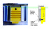
Imgill's idea for the locking spring
Screw used is M1,6x2,5


Screw used is M1,6x2,5
antarusfree
Well-Known Member
antarusfree
Well-Known Member

Similar threads
- Replies
- 5
- Views
- 6,722
- Replies
- 25
- Views
- 4,925
- Replies
- 117
- Views
- 26,256
- Replies
- 1
- Views
- 1,247