Poikilotherm
Sr Member
Deleted
Last edited:
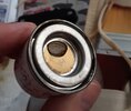
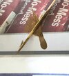
neeeaaat, I didn't think of this, but yes the crucial part of the switch is not the casing of the switch!View attachment 1383815View attachment 1383816
View attachment 1383819
View attachment 1383821
I'm not sure what flicker trigger you'll ultimately choose, but if you use the same switch and want to trigger by pressing the board, I can give you some advice.
DaveP Hero PCB Reveal Boards are great, but if you use the inner steps of the Hero box to hold the board in place, you need to trim the switch.
If you do not trim the switch, you will not be able to trigger the flicker by vertically pressing the board.
After I trimmed it and tried it, it was still working.
Hope these have been useful to you!")
I just connected the parts to the board, soldered the wires on the back, and watched on one side how to use the display board to trigger the switch.neeeaaat, I didn't think of this, but yes the crucial part of the switch is not the casing of the switch!
1) I'm going to try trimming one of my snap switches - is that just raw board that you can stick things in to test them without soldering? omg I have a lot to learn
2) at some point the research discussion will continue because dave is super swamped, and I'm getting the feeling they didn't chop up a switch to do this
That looks great Tom. Proportions look pretty good. Couple of minor things you might want to change for complete accuracy: the pommel is a bit more detailed. The cubes have a small parallel step before sloping and the gap between them is flat. This should actually make machining them a lot easier. Also, the step down to the pommel from the booster looks a little bit too deep. I'd just check your design against some of the side on references. Your grenade section looks spot on (although it's worth saying every ring should be unique; many replicas have just two different thicknesses). Overall proportions look great though. If you want to be super accurate, I'd consider building your control box rails in four parts (2x T profile and 2x L angle). And something that is often overlooked, the screws should be at 22:10. All in the detailsView attachment 1427334
Hi Folks, I'm new here and to the community, this is my first project like this, and only 4th project on my lathe so please ignore my ignorance. I made up some designs from what I have researched to make on the lathe which I started today (See picture). I know its been done a million times before, but I wanted to get some opinions from others. Any constructive criticism is muchly appreciated. See attached drawing.
Thank You, TWB.
View attachment 1427336
Thank You for your reply, and thd9791. I have made my own thread: Luke's RotJ Hero Lightsaber Build for the project, and will keep it updated with my progress!!That looks great Tom. Proportions look pretty good. Couple of minor things you might want to change for complete accuracy: the pommel is a bit more detailed. The cubes have a small parallel step before sloping and the gap between them is flat. This should actually make machining them a lot easier. Also, the step down to the pommel from the booster looks a little bit too deep. I'd just check your design against some of the side on references. Your grenade section looks spot on (although it's worth saying every ring should be unique; many replicas have just two different thicknesses). Overall proportions look great though. If you want to be super accurate, I'd consider building your control box rails in four parts (2x T profile and 2x L angle). And something that is often overlooked, the screws should be at 22:10. All in the details
Awesome job Tom. I'd love to follow your project if you posted your own thread!
I spent months trying to find it Tom, believing that it was either a rocker (channel up/channel down) switch, or possibly a slider cap. As Bryan said, it did used to be straight, so I think it was originally one piece. I assume it was damaged the same time as the rails and red triangle.I know we've beat some of these things to death, but I am in the process of making my own black buttons. What are everyone's theories, beyond what has been found here already?
I've seen them sit at different angles suggesting they're separate, but then what is this in between?
View attachment 1438076View attachment 1438077
Also, found part or real...
is there something behind them? (look on the right side)
View attachment 1438075
but I'm learning to love hand made finishes (click for larger)