Zombie Killer
thanks
thanks
Last edited:

Thanks Chris! You truly are a mine of information!It’s an Icons prototype. I have pictures somewhere. I’ll see if I can find them.
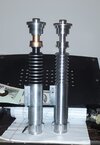
Here you go:
View attachment 1349148View attachment 1349149
View attachment 1271287
Sorry for the delay; this is a bench test.
3V power (two watch batteries)
SPST > SPDT snap action > blinking red/green scale train signal light LEDs > common negative to power.
I’m not saying this is THE setup; in fact it’s pretty messy (relative to another member who is also working on this)
I’m trying to figure out how to alter the timing parameters on these LEDs because (unlike their data sheet implies) they haven’t been speeding up or slowing down with voltage variance. A simple IC is built in on these; so considering built in IC, no resistor necessary, and only 3V required i think they could all certainly fit inside the box: and at MOST require a milled area in between the mounting screws for the 3V battery to sit.
These particular LEDs can take 14V unresisted...
I still need to assemble my photos for the other issue in question thd9791
Not wicked? Darn! We failed.Sexy
Not wicked? Darn! We failed.
Haha no it only counts if Halliwax says it. Hahahah!!!That's wicked, yo.
...Better?
Yeah THERE it is!!!!Wicked sexy!