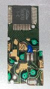
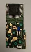
Magic of Myth ( MoM ) Luke RotJ Hero ( cave build ) lightsaber research, images, reference, & collaborative model builder's discussion.

I worked on making some 3.5 mm hand formed brass today to try and flesh out this concept from the ground up.

Using basic tools available to a shop-
1- Vintage vector board cutoff or one of my replica clamp cards.
1- sheet strip of 2" (1/64" or 0,42mm brass)
- a flat, sharp vise (or these 8" Irwin grips)
- Mill ******* File
- hobby knife
- hand shears for metal (smooth edge important)
- Flat faced hammer
- Calipers
- Sanding block
No description available.


I'll try and re-create the process and update this at a later time with more pictures/ video.

Use calipers to initially scribe your fold and cut lines on the brass. In my case, I scribed a line at 3.5 mm and 7mm.


- define the fold line by scoring the 3.5 mm line a couple times with the hobby knife- which creates a straight and shallow valley.
IMG_5081.jpeg

- clamping the uncut material at the 3.5 line it can be folded by pushing it sharply on another hard surface.
IMG_5082.jpeg

- Once folded, hammer it down to the vise surface to flatten it to 90 degrees.
- Once the fold is sharp, you can re-scribe 3.5 mm with your calipers on both sides.


- Using the metal shears, you can trim off the excess- and separate the angle from the rest of the material.

If there is any rough edge, or the thickness still needs to be reduced, you can clamp the L material and file it to the size you're looking for.

Once complete, you'll be able to use a square surface to additionally (very lightly) hammer out any deformations. In my case I used my small machine square. I imagine a machinist/ jewelers vise would work much better for some of these processes.

Here is the result:
No description available.


No description available.

No description available.

and, using the vintage vector card.. just to confirm that I hit the sizing I was looking for in my collage app.


Worth noting the overall box width/ seen above is subject to the idea the rails were already falling off/ reglued.

And I also just had an epiphany about the setup of plastruct I’ve been using…. I’ll have to make another set but it is the same materials.
 
Last edited:
Method 2:
IMG_5104.jpeg

As before:
- Brass
- Calipers
- Shears
This time add:
- *thick* leather
- heavy hammer
- freshly sharpened 2” masonry chisel.
- a robust base to hammer on

The flatness and sharpness of the chisel is absolutely imperative for a clean fold. I sharpened this chisel with my mill file prior to this process.
IMG_5105.jpeg


Step one:
As before mark your 7mm and 3.5mm lines.

Step 2.
Lay the brass flat; line up the sharp chisel edge on your fold line, and with a decisive heavy vertical strike you’ll set the fold.
I’ve been working both sides of the brass at the same time.


Step 3:
Now that your fold is set position the brass a second time, for a second strike.
You may, or more may not need more or less to achieve a 90degree bend.


Once complete: you will have a very smooth ,well set fold- avoiding the hammer marring.

To finish you’ll simply need to shear the L at the marks and clean up with a file, performing any light re- shaping necessary afterwards.
IMG_5103.jpeg
 
Last edited:
I’ve had bad edges using tin snips to cut thin metal - what is the difference with shears? How do you cut in a straight line down wide material?
 
Haha, we chatted.
The shears I bought are well over 2” and straight cut (not serrated).

They more closely resemble the edge of a Beverly shear… (the tool I imagine they would have used) which is a common tool in any well equipped shop.
 
I totally understand now. And feel less silly, thinking I was using the right tool in the wrong way lol

I'm of the belief that the wall behind the triangles has been removed, I'm going to have to document my build a little here
 
Based on the spacing, the green arrow appears to be wedged against the front of the SPST slide switch. With room for a green 3mm LED behind it.
Poikilotherm has already worked that bit out- and is pretty close to finishing a working contained box with a 555 timer, capacitor… and the last element is the boba fett style rangefinder SPDT
oh yes we've talked! I've got a couple of those switches too! Its a fun puzzle. I was thinking yesterday I wonder if they used the housing for the 785 battery inside the prop... I guess you wouldn't need to change out the battery for just the one scene, I'm thinking of myself I guess lol

I wonder if the red one was just as long, if it was shorter, you'd stagger the LEDs and maybe have a little extra room lol
 
Good lord. Do we have any proof of how far the green prt goes behind the slide switch?

For my build I’m going to cut and shape colored acrylic and affix a blinking LED behind them or something.

Everyone has a different view of what's in a control box, and perhaps all the components in a hero control box are glued internally and not held in place using soldered plates. Initially I found red triangular led's of similar size, which could be trimmed to fit directly into the side panels, and this is what I use to this day. Green triangles I've been using the 617 model.

If you're getting started on your control box these days, thought I'd have a few things to share with you, I recently put a 555 into a Hero control box with plenty of space and upped the voltage to 4.5V. of course it can flash at 3V but not very brightly. The adaptive blinking led does get good results at 3V, but it gradually blinks slower as the battery power decreases, so it doesn't reach the standard line specified for 3hz blinking. Because it uses a battery, the blinking rate is not as fast as expected at 3hz per second with a full charge, so if you're interested in building it with a 555 that would be great.

The green triangle must be stuck at the switch, but not sure of the length of the switch pins maybe it's stuck at the pin location or maybe it's stuck above the pins. [The switch on the exactra19 allows the green triangle to snap into the correct position]

I have a couple of photos taken while building the control box, as well as photos of building the 4.5V battery base and photos of the space taken up by the 555 in the control box. :p[I know you have a DaveP control box, and the DaveP control box is a different height dimension than the MOM control box, so I pulled out my early DaveP control box and tested the 555 for you to see if it would work, and the answer is yes. :p ]


20240124163824.jpg.png
20240124163825.jpg.png
20240124163826.png
4.5V 1.png
4.5V 2.png
2012445621725.png
20240124167773.jpg.png
20240124172922.jpg
20240124163823.png
20240124172518.jpg

20240124163813.jpg
20240124163823.jpg
 
Last edited:
I had a couple of breakthroughs / epiphany moments yesterday.

1st:
I believe a third method for the L Brass rail may well be the method used.
- - I need to get another piece of brass angle so I can properly show it.

Lightly asymmetric, sharp, straight lines and corners, very little deformation… but that will be what we need to dive into ;)

Suffice to say I wouldn’t do it any other way now: allowing that a proper machine vise is accessible.

2nd:
Eureka! … related to Poikilotherm’s and my collaborative efforts to understand the box construction. Just teasing it now: but it does feel like it changes everything (in a good, confirming way)
 
okay okay okay
I don't know why this is my first time but I've been flipping between these photos and its amazing what matches when you do. All the brass and death star and solder bits are there. But I do have an unfinished idea.
Untitled.jpeg
Screen Shot 2019-05-24 at 4.24.53 PM.jpeg


I now am totally convinced the board is cut straight in the center of the back. Whether thats for a component or some other dull thing I'm not sure. I'm guessing the cut goes as far back as the gold plated blue resistor board piece... but how far right? Are the two pieces on the right covering the original board or is the whole right rear half removed?! Someone with more knowledge please help.

Also, in this shot it doesn't look like the right rear corner is much higher than the rest. That white resistor isn't too proud
Screenshot 2024-02-04 at 1.13.07 PM.png

IMG_1445.jpegIMG_1443.jpeg
 
Last edited:
View attachment 1785893View attachment 1785894

I now am totally convinced the board is cut straight in the center of the back. Whether thats for a component or some other dull thing I'm not sure. I'm guessing the cut goes as far back as the gold plated blue resistor board piece... but how far right? Are the two pieces on the right covering the original board or is the whole right rear half removed?! Someone with more knowledge please help.
You are correct, the lower right corner of the 785 board is partially trimmed and taped to the main part rather than to the untrimmed 785. There is a much clearer version of the first picture, from that position you can see the aluminum colored bottom of the control box, in recent weeks Bryan and I have tried and got excellent results, there is a major fitting there that drives the red and green triangles inside the control box, the overlay plate covers the top of the major part, the correct fitting and the correct height of the control box is what will give you the correct height of the board.

Secondly there are a few more issues to explore, I am currently abandoning the use of modern light emitting diodes, I would say that even if we really understand the components inside the control box to make something that is exactly the same, because the wrong choice of red and green led can result in the final blinking effect being incorrect, I don't know why modern light emitting led's have so many different effects, Voltage / Light Emitting Range / Low Brightness/high penetration/high voltage/low penetration/two different penetration effects of light emitting leds will be on the same fitting with a noticeable difference in the speed of operation or rather the size of the response.

One more thing, this is all serendipity. I have now moved away from the 1SX1-T and am using a more primitive structure to trigger the red led, it doesn't make any sound when triggering the red led, the process of activating the red led is shorter, switching to the green led is more natural, and the switch doesn't show up in the camera when photographing the control box circuit boards unless we look at it with a magnifying glass. [The video is at the bottom!]

When I made this I saw some of the differences in the modern lighted led [this is also a test for other enthusiasts in the community who think that the sound in the deleted footage was added later], although it could be controlled by moving it closer to the 785 stack or through the energized wire area of the 785 main circuit board. But I'm not doing that at the moment, unless there are new references to three wires or solder joints under the left side of the board that I would connect to the 785 board, but it's very possible that the wires or solder joints I'm talking about are under the left side of the board, as that board is bonded higher than the normal height of the board.

Progress is still being made and I'm sure Bryan will follow up with these announcements when the time is right.

The non-existent test in the lower right corner indicates the image , tape is attached to the main accessories, not to the 785 board. [I want to make it clear in advance that if there is a difference in the height dimensions of the control box itself please don't do this .......]
20240218153625.png


Please ignore the order in which the accessories are placed, only for testing the red and green led glow/flashing/response speed/brightness/penetration test. If you can see the difference between the red and green blinking I think this information will help you on your current build of the 785 board!


Last edited:
IMG_4874.jpeg
IMG_4872.jpeg
I’m pretty sure that is a blanked hole. Not sure if it’s solid metal or a screw that was blanked, but my belief is that was the second grub screw holding the tang of the Yuma blades

Maybe for molding or just to clean the saber up for closeups they drilled and hammered in aluminum round stock or cut the head off a screw
 
It should be no secret I believe the originals are the brass rails used in ISYHCANL that were sprayed with the V3 neck color (or similar) and subsequently touched with additional copper paint prior to most of our reference photos
Ok thank you :) it was hard for ne to tell in the pictures
 

Your message may be considered spam for the following reasons:

If you wish to reply despite these issues, check the box below before replying.
Be aware that malicious compliance may result in more severe penalties.
Back
Top