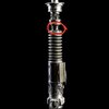
DaveP's Luke RotJ V2 Research/Development Thread 2021

WOW! Switching to second shift hasn’t left me a lot of time to stay up to date on everything! But after reading all of this (and some what processing it) Between Halliwax’s demonstration, and Dave’s organized explanations, I believe all of this makes sense so far…. I’ve always been on board with the break-neck theory. I’m currently a machinist, and I machine foundry cast brass parts. It is NOT uncommon to see parts break in weaker areas, and have to be revised by engineers. It is obvious that the neck groove would be the weakest point, and castings, (metal or not) as shown in Danny’s demonstration, CAN break like ice just by dropping them on the ground…So to assume the necks broke this way, (especially in such a thin area of rather porous aluminum) and that they assumed their initial more solid form in ANH (as more of a unibody design) is not a jump by any stretch of the imagination. I believe most of all, Dave has made it clear with his compiled research he’s been willing to (and has) changed his mind multiple times in this design, to arrive at an internally and externally accurate prop, as close to what we see on screen as possible. Thanks for all of this Dave! Happy to be apart of this run, and even more happy to see all of this research laid out:)!
-Ariston
Hi Guys - I've only just come across this awesome thread! And funnily my own project recently trying to figure out and /or replicate some of the exact issues being discussed right here. I had followed Vadermania's ANH Obi Wan special effects lightsaber replica project thread back in May last year and having my father in law (who is an old school lathe genius) make several saber bodies for me - had set about my final dream project to get a motor inside an Obi Stunt and just get it working! - With a few teething and communication hiccups (due to Covid travel restrictions last year) we managed at last to get it done - almost when I had just given up - (everything was in place, but just could not get the motor to turn! - I decided to just change to motor to a slower but more powerful one running off a 9V battery instead and it finally worked!)
Reading on all the research pages here is coincidental as I had just left the inner arrangement to my father in law - who just did the inner design to suit what we were tring to do - no bushes or bearings at all - the emitter spins as I had thought (from Brandon's description of the V2) attached straight to the tang rod which is secured either side with grubscrews into the nipple. the other end inside is attached to the motor end with a small brass section held with grubscrews - I had mentioned about maybe trying to fit a bearing inside the emitter end but my father in law had machined a small thin sleeve on the end on the neck at the body section that located into the emitter end of the neck - which he said would act like a bearing anyway (I now appreciate the engineer's thinking approach with this project which is likely more like the propmakers - get the job done and make it work the most straightforward way!) - the motor and tang were not quite aligned but the torque of the motor seemed to overcome any friction or slight misalignment issues almost immediately - I just added an extra grubscrew under the clamp straight through the body to hold the motor in place. There is no sticking or jamming and it turn easily without a rattle when held up or side on.
(I filmed a short 30 second video of it working which hopefully is viewable as mp4 here below)
Very pleased with the results! (to say the least) plus I got to use a Roman's pommel that was the starting point of the whole project (the only piece other than the clamp combo that we were unable to make as we don't have a milling machine)
The broken neck theory makes perfect sense and I'm sure this version would spin in the same way without the improvised bush joint in the neck.
 

Attachments

  • VID-20210725-OBISTUNTWORKS.mp4
    8.7 MB
Last edited:
Forgot to add too that the motor I used was from a type noted in a discussion thread on the V2 (but can't remember which!) - but the motor type was from amazon and pretty cheap and can be found by looking for - HALJIA DC 6V 120RPM High Torque Permanent Magnetic DC Gear Motor Micro Gear Box Motor Speed Reduction Electric Gearbox Eccentric Output Shaft - the size was pefect for fitting into the body cavity - this one is 6V but the one I received ran great off a 9V battery - it was held in with some thin card shims (as per Vadermaina's thread notes - thank you by the way for the great research thread!) and then secured with an extra grubscrew to stop it turning when the battery is connected.
 
Last edited:
Hi Guys - I've only just come across this awesome thread! And funnily my own project recently trying to figure out and /or replicate some of the exact issues being discussed right here. I had followed Vadermania's ANH Obi Wan special effects lightsaber replica project thread back in May last year and having my father in law (who is an old school lathe genius) make several saber bodies for me - had set about my final dream project to get a motor inside an Obi Stunt and just get it working! - With a few teething and communication hiccups (due to Covid travel restrictions last year) we managed at last to get it done - almost when I had just given up - (everything was in place, but just could not get the motor to turn! - I decided to just change to motor to a slower but more powerful one running off a 9V battery instead and it finally worked!)
Reading on all the research pages here is coincidental as I had just left the inner arrangement to my father in law - who just did the inner design to suit what we were tring to do - no bushes or bearings at all - the emitter spins as I had thought (from Brandon's description of the V2) attached straight to the tang rod which is secured either side with grubscrews into the nipple. the other end inside is attached to the motor end with a small brass section held with grubscrews - I had mentioned about maybe trying to fit a bearing inside the emitter end but my father in law had machined a small thin sleeve on the end on the neck at the body section that located into the emitter end of the neck - which he said would act like a bearing anyway (I now appreciate the engineer's thinking approach with this project which is likely more like the propmakers - get the job done and make it work the most straightforward way!) - the motor and tang were not quite aligned but the torque of the motor seemed to overcome any friction or slight misalignment issues almost immediately - I just added an extra grubscrew under the clamp straight through the body to hold the motor in place. There is no sticking or jamming and it turn easily without a rattle when held up or side on.
(I filmed a short 30 second video of it working which hopefully is viewable as mp4 here below)
Very pleased with the results! (to say the least) plus I got to use a Roman's pommel that was the starting point of the whole project (the only piece other than the clamp combo that we were unable to make as we don't have a milling machine)
The broken neck theory makes perfect sense and I'm sure this version would spin in the same way without the improvised bush joint in the neck.
What a cool project! I love seeing family builds like this. :) The fact that it's mostly scratch built is pretty awesome too. Turned out great!

That motor is very similar to the one I'm using actually, although I've gone with a higher speed to try to match the 20:1 gearbox that Jon Bunker mentions in vadermania 's thread.

I am toying with the idea of securing the motor with a grub screw under the clamp too for the motorised stunts. I highly suspect that there is probably something like that on the actual prop, although impossible to say for sure. There's mention of paper shims like you said, but I do worry that without the grub screw, the motor could spin inside the chamber and twist free from it's connections. I used electrical tap to shim the motor on my previous test, which did a decent job, but it is something that's playing on my mind a little.

The sleeve you mention at the neck that acts as a plain bearing sounds very similar to the bushing that I was planning on having there until a week or so ago. It would make perfect sense to have that there if the emitter was separate to the body at the time. It's amazing how fast things can change, and you've done a fantastic job with the information that was available! (y) Finding out that there is no sleeve/bushing at this point is what led to the conclusion (suggested by Halliwax ) that the body and emitter must have been one single piece. The interference/friction at the join (especially when the weight of the blade is added in to the equation) would just be too great for the mechanism to work effectively.

Anyway, great work! That really is something that you can treasure. :)
 
*Update*

Hi everyone. With all the parts ordered for the run, I've moved on to colour testing for the Motorised Stunt...

I'm planning on getting one of my spare Yuma bodies painted as a physical test, but the weather here is just awful this week and not playing nice!

So yesterday, I did this study:

ANH PAINT TEST.jpg


The prop is seen in various different states, and as mentioned previously, there are a number of references that are NOT the Motorised stunt.

If you look at the mock-up I've done, you'll notice that the the emitter and grenade section are not completely black (The booster is). I'm planning on using black as a base, then applying "oil rubbed bronze" to the grenade and emitter sections. This is VERY dark, but not quite black. For the accented neck section, I'll be applying "Bronze Gold" along with the base coat, before applying the "Oil Rubbed Bronze" The plan is, that I can then gently knock back the top coat to reveal some subtle highlights.

I'm going to attempt to do this freehand, as I'm not seeing any sharp transitions in colour. This is an experiment at this stage, and I'll look forward to sharing the results (as soon as the weather will allow!) :)

I have taken the colouring on the prop as it is today in to account of course:

ref narrow.jpg


I do wonder how much the saturation of colour has changed over time? That said, there does appear to be a subtle hint of dark bronze still towards the neck end of the grenade section and on the emitter.

I'm very much open to suggestions on this, and would love to hear people's thoughts. (y)

Thanks for looking everyone.

All the best and MTFBWY,

Dave
 
0B7F3D6A-A682-4662-9A81-4DC39F707E54.jpeg

Hey Dave! Here’s a test I did on a spare V2 body I had
1) Everything is done with rustoleum flat black
2) I aggressively handled/rubbed the rings and emitter… like it would have been on set. This dulls out the black a bit
3) dry brushed the neck with rustoleum flat brown. Repeated lightly until desired color was achieved

Can’t wait to see your method and compare results!
 
Last edited:
View attachment 1505187
Hey Dave! Here’s a test I did on a spare V2 body I had
1) Everything is done with rustoleum flat black
2) I aggressively handled/rubbed the rings and emitter… like it would have been on set. This dulls out the black a bit
3) dry brushed the neck with rustoleum flat brown. Repeated lightly until desired color was achieved

Can’t wait to see your method and compare results!
That is a starkiller Gen1, if you ever want to let it go please contact me
 
*Update*

Hi everyone. With all the parts ordered for the run, I've moved on to colour testing for the Motorised Stunt...

I'm planning on getting one of my spare Yuma bodies painted as a physical test, but the weather here is just awful this week and not playing nice!

So yesterday, I did this study:

View attachment 1505001

The prop is seen in various different states, and as mentioned previously, there are a number of references that are NOT the Motorised stunt.

If you look at the mock-up I've done, you'll notice that the the emitter and grenade section are not completely black (The booster is). I'm planning on using black as a base, then applying "oil rubbed bronze" to the grenade and emitter sections. This is VERY dark, but not quite black. For the accented neck section, I'll be applying "Bronze Gold" along with the base coat, before applying the "Oil Rubbed Bronze" The plan is, that I can then gently knock back the top coat to reveal some subtle highlights.

I'm going to attempt to do this freehand, as I'm not seeing any sharp transitions in colour. This is an experiment at this stage, and I'll look forward to sharing the results (as soon as the weather will allow!) :)

I have taken the colouring on the prop as it is today in to account of course:

View attachment 1505004

I do wonder how much the saturation of colour has changed over time? That said, there does appear to be a subtle hint of dark bronze still towards the neck end of the grenade section and on the emitter.

I'm very much open to suggestions on this, and would love to hear people's thoughts. (y)

Thanks for looking everyone.

All the best and MTFBWY,

Dave
So towards the grenade section on the prop as it is today, I feel like I’ve always been able to
see a bit of the burnt color on that section of the neck as well. What are your guys’ opinions on this section?
 

Attachments

  • 6A5B4ACF-3D11-4B2E-9012-5D15B5479999.jpeg
    6A5B4ACF-3D11-4B2E-9012-5D15B5479999.jpeg
    93.2 KB · Views: 114
Has it been considered that the niple part might be a gear shaft, could it be from the original motorised build?
gear-shaft-500x500.jpg

Might the blade fit over this and be locked with a grub screw?
 
Has it been considered that the niple part might be a gear shaft, could it be from the original motorised build?
View attachment 1505368
Might the blade fit over this and be locked with a grub screw?
I wouldn't rule out that it's a found part entirely. The only thing is, it certainly looks to be the same material as the rest of the hilt in all of the reference materials. Brandon has said previously, he wasn't sure if it was even a separate part. I've explained why I'm fairly certain that it is, so won't go in to that again. It could well be a pre-existing part from something though, sure.

We do know that the Obi Motorised Stunt blades weren't like the other stunt blades though. They didn't "fit over" the nipple, and didn't have collars. The tang was a part of the mechanism (not the blade), and protruded from the emitter/nipple before attaching the blade (which was pressure fit).

I assume (it is an assumption) that the step in the nipple was simply to make the protruding part closer in diameter to the blades that were being used. The part that was bellow the emitter face was closer to the bearing size.
 
View attachment 1505187
Hey Dave! Here’s a test I did on a spare V2 body I had
1) Everything is done with rustoleum flat black
2) I aggressively handled/rubbed the rings and emitter… like it would have been on set. This dulls out the black a bit
3) dry brushed the neck with rustoleum flat brown. Repeated lightly until desired color was achieved

Can’t wait to see your method and compare results!
Looks like a V3 emitter...is that Jorges with the starkiller?
 
*Update*

Hi everyone. With all the parts ordered for the run, I've moved on to colour testing for the Motorised Stunt...

I'm planning on getting one of my spare Yuma bodies painted as a physical test, but the weather here is just awful this week and not playing nice!

So yesterday, I did this study:

View attachment 1505001

The prop is seen in various different states, and as mentioned previously, there are a number of references that are NOT the Motorised stunt.

If you look at the mock-up I've done, you'll notice that the the emitter and grenade section are not completely black (The booster is). I'm planning on using black as a base, then applying "oil rubbed bronze" to the grenade and emitter sections. This is VERY dark, but not quite black. For the accented neck section, I'll be applying "Bronze Gold" along with the base coat, before applying the "Oil Rubbed Bronze" The plan is, that I can then gently knock back the top coat to reveal some subtle highlights.

I'm going to attempt to do this freehand, as I'm not seeing any sharp transitions in colour. This is an experiment at this stage, and I'll look forward to sharing the results (as soon as the weather will allow!) :)

I have taken the colouring on the prop as it is today in to account of course:

View attachment 1505004

I do wonder how much the saturation of colour has changed over time? That said, there does appear to be a subtle hint of dark bronze still towards the neck end of the grenade section and on the emitter.

I'm very much open to suggestions on this, and would love to hear people's thoughts. (y)

Thanks for looking everyone.

All the best and MTFBWY,

Dave
You had me at spare Yuma lol...
 
What if they had to cut the emitter off to repair the bearing that was in there or ... remove the motor assembly? The bearings would most likely be pressed fit in there....Maybe the motor was press fit in too? ( just read about the shims lol) Or even after some time with extreme force with stunt practice , since it is a cast prop, threw the assembly out of alignment? That would be a good reason to cut the emitter off at that seam... just a thought
 
Last edited:
So towards the grenade section on the prop as it is today, I feel like I’ve always been able to
see a bit of the burnt color on that section of the neck as well. What are your guys’ opinions on this section?
I believe when the V2 was painted in ANH.. the coloring was supposed to mimic the worn brass color from the wind vane and neck area.. ( makes sense to me ) I see what you see and I’ve even added brownish tones to my neck there too on my replicas
 

Your message may be considered spam for the following reasons:

If you wish to reply despite these issues, check the box below before replying.
Be aware that malicious compliance may result in more severe penalties.
Back
Top