DaveP's Luke RotJ V2 Research/Development Thread 2021

They went to the trouble of brushing on a darker brown tone for the neck of the V2 that was barely noticeable - another rattle can of gray isn't that out of the water to me. Also, I've experimented with 3 Tamiya Lacquer cans (something that was available back then in the model shop) and got some of the same colors on my own hilt *shrug*

notably the other stunts had different paint jobs too, I'm not sure they had heavy attention to detail either
 
**Update**

Sorry everyone... I've been so insanely busy these past couple of weeks, that I've just not been able to contribute to the discussions on my own threads!

So many separate conversations in my DMs regarding the run (which is now closed)... I'm still incredibly busy though, ordering parts and materials as well as various ongoing discussions which I now need to discuss here.

I'll just cover some of what's been discussed in my absence first...

BeFunky-collage (5).png


As 
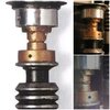
Halliwax has said, the top left image on this collage is NOT the V2. At the time of making the collage, I knew that the clamp was missing and that it was held together with gaffers tape (that's not paint from what I can see), and that the whole thing was kind of wonky, but I did think that it was the V2 at the time. Or at least parts of it were.

As scarf man has pointed out though, the pommel is clearly different!

As for the paintwork, I only had one V2 kit available to me for paint/stencil testing and it was used to build the ROTJ version of the prop.

I WILL be doing a test run of the paint scheme for the ANH version though. I'll be applying this to one of my spare Yuma bodies in the next couple of weeks.

As always, I'll be more than happy to share the Brands/Colours that I settle on once I'm fully satisfied (y)

**Important!**


This week I began a conversation with someone VERY closely connected with the original prop...

surprise-welcome.gif


They have asked to remain safely anonymous, but I can assure you that this information comes on VERY good authority...

It was my plan to begin ordering parts for the run on Monday, but this new information came to light and it looked as though design changes would be needed, so for that reason, I held off from ordering the CNC'd parts while the conversation was still ongoing.

It's my hope that everyone on the run will agree with me, that it's better to have a short delay, than to have an inaccurate replica!

So.... What's new?...

The emitter as it is today is one, solid piece... This is something that I found very difficult to accept at first, but I believe I may have an explanation...

I was already aware that Brandon Alinger (the props current owner) had not been able to disassemble the emitter/nipple part, based on one of his quotes, but I had put this down to the screws being locked up, or that perhaps some sort of adhesive could possibly have been used to fix in the non-spinning blades that were used during practice (behind the scenes on Empire)?

Having had this detail confirmed via another source has helped to build up a picture of what might have happened.

This is all very speculative of course, but I wonder if the reason that there appears to be a smooth, unbroken shaft running through the middle is because any breaks or detail have been filled by adhesive?

For me, it just isn't possible that the emitter began life as one single piece. Here's why:

  • I very much doubt that it would be possible to machine the gap in the emitter plate that is present around the nipple. If it were, I can see no reason for doing so? It could be that the plate itself is separate to the rest of the emitter, but with no evidence of how it could have been fixed in place, and no other visible breaks, I've steered away from this idea. I've also had it confirmed that this was not the case.

  • There is no evidence of the nipple ever having been painted either, which just steers me a little further in the direction of it being a separate piece.

  • The second set of set screws that cross that gap suggest to me that they could potentially have been holding the two parts together, or that that was at least their original purpose?

I believe that there was almost certainly a bearing housed within the emitter back in 1976. I believe this for a number of reasons:

  • It would make sense from a design/engineering perspective

  • The gap around the nipple (again) and the diameter across the opening (as well as the diameter of the rod) correspond to a very common ball bearing size. The gap implies that the size of the opening was more important than avoiding a gap. If that makes sense?

  • The thing with my V2 run, is that the parts have to work as both the V2 as is is today, and the motorised stunt as it was back in 1976. Having experimented with different mechanisms, and spoken with a few others who have successfully built working motorised hilts, we've all experienced the same issues when any friction is introduced in to the system. Just holding the blade horizontally with only a single bearing locks up the mechanism. Whereas, with two bearings, the rod is prevented from coming in to contact with the walls of the hilt.

The fact that the emitter appears to be one solid piece today, does not necessarily require any design changes on it's own. As I've explained, it's my belief that the whole thing has been cemented together, sometime between the filming of Star Wars and ROTJ.

CUTTAWAY ORIGINAL.jpg


Current design.

CUTTAWAY ORIGINAL FUSED.jpg


Current design (Fused)

I have it on good authority that the second set of screws are now missing from the emitter. This is something of a revelation to me, as I was previously certain that they could be seen in the gap. If these screws failed at some point, perhaps this is the very reason why the emitter and nipple were cemented together? Perhaps adhesive was necessary on account of these screws no longer working as they should?? What I thought were screws that could be seen in the gap around the nipple could well be the imprint of them in whatever adhesive was used? Perhaps the already failing screws were used to hold everything together whilst cementing?

Another detail that I was unaware of is that the second set of screws stopped AT the nipple, locking on to the side, rather than having a second set of threaded holes. This, again is on good authority and will require a slight change in the model. Literally a couple of clicks of the mouse to remove these, so nothing too time consuming.

One more thing... and this is a big one...

There is NO bushing at the neck join. o_O I really, really want there to be, but again, I have it on very good authority, and from a reliable source, that there just isn't one there...

As I said earlier, holding the prop horizontally did put a strain on the mechanism, which is why I felt that the bushing was needed. On reflection though, It could explain Sir Alec Guinness's unusual grip on the prop during filming! I always suspected that he was preventing the emitter from spinning, but perhaps it had more to do with keeping everything in line and avoiding too much friction between the rod and the neck opening??

It kind of makes sense:

cropped.jpg


It's not ideal, but as we know, these things weren't always made in the best, most practical way, and were often made to tight deadlines, experimenting along the way. It's far more important that this replica is an accurate representation of the original prop. I suspect (hope) that this is a view shared by those who have taken part in the run.

Better to have a perfect replica of an imperfect prop! :)

So, based on this new information, the updated design will look something like this:

CUTTAWAY NEW.jpg


And today, with everything cemented together, the Emitter looks something like this:

CUTTAWAY NEW FUSED.jpg


Please excuse these crude diagrams (*which are not drawn to scale). I really don't have the time to render new 3D cut-aways right now, as I need to get on with updating the models for the machine shop. I will get some nice new renders made soon though and update the original posts in the thread.

**Just a note for anyone who is on the run, and may be concerned about any delay, these changes are relatively easy to make to the existing models, and should be done TODAY.**

Thanks for your interest everyone, I hope you find these new revelations as interesting as I do! I really do feel that we're not only building up a picture of the actual prop, but of it's history and the changes that it's gone through over the past 45 years! :)

All the best,

Dave
 
Last edited:
While it means it might take slightly longer to receive a finished product, I for one really appreciate your willingness to continue improving and listening to input. A lesser maker would have just carried on with the run and not bothered with details that we would never be able to see.

This is why I want this run so badly, because whenever I hold it in my hands I will know that it is the closest thing to the original that we know of up to this point.
 
You know, it does actually make sense for the emitter to have been permanently bonded together at some point once the thing transitioned to being essentially just a spare stunt and didn't need to spin anymore
 
"There's more. It won't be easy for you to hear it, but you must..." - Luke Skywalker

I hope you're sitting down... :D

So following yesterday's revelations I got talking behind the scenes with community legend, Halliwax.

Neither of us were particularly happy about taking the bushing out of the equation. It just doesn't appear to make sense from an engineering point of view. The emitter would have to have been kept perfectly in line with the body section, all whilst delivering a performance. ANY introduction of friction between the central rod and the opening of the neck would grind the mechanism to a halt. This is something that we've both experienced first hand.

This isn't about personal preference. This is about arriving at the truth, and something just didn't seam to fit with what we see on film.

Then Danny suggested something that at first made me want to cry, but after the initial panic subsided, made perfect sense!

What if the emitter and body were one piece on the motorised stunt?...

My first reaction was absolute terror! How would this effect the run?? I have two different versions of the prop on my run! I'd have to produce a full ANH section as well as the separate body/emitter sections for the ROTJ version. Having thought about it, this isn't such a huge problem. I'd just have them all machined together and break them up myself. I'd end up with a few extra body sections where people have ordered additional emitters, but that's not the end of the world.

It never really made any sense for the emitter to be separate. I've spent countless hours looking for evidence of it spinning prior to ROTJ, and come up with various theories as to how and why it was prevented from doing so.

Now that we know that there is no bushing present, it absolutely makes sense that the original prop was one single piece, with a bearing at either end of the neck section:

SOLID CUTAWAY.jpg

*NOT DRAWN TO SCALE*

Evidence...

I set out to test the hypothesis, looking for evidence... It didn't take long to find some:

SEAM LINE.jpg


I believe that what can be seen here is a seam line bridging the gap between the emitter and the body. Just as we see in the original castings (from which both the V2 and V3 were made)

I really should address the image that convinced me there was a bushing in the first place, and that the emitter was a separate part. It would be wrong of me to just sweep it under the carpet and pretend that it didn't exist:

5.jpg


I WAS convinced that what could be seen here was an exposed section at the neck join, that was considerably thinner than the neck, but thicker than the internal rod. This is what led me to believe that there was indeed a bushing at the neck join.

It seems I was a victim of my own confirmation bias. When you actually dig in to this image and mark in where the geometry of the prop *should* be, it becomes clear that bloom from the lit panel behind is not only effecting the neck section, but also eating in to the wind vane and the emitter:

BLOOM.jpg


Interestingly, the emitter being joined to the body section also fits with Jon Bunker's drawing and description too.

There is no mention of the emitter spinning, and importantly, no reason for it to have done. In fact, it would have served no purpose whatsoever.

I'm now 100% convinced that the motorised stunt body/emitter were one single piece, which is why the mechanism worked so well. The internal rod was suspended between two perfectly aligned bearings, keeping it from coming in to contact with the hilt.

I believe that it was then converted in to a static stunt prop for use behind the scenes on Empire, at which point it was stripped out and cemented solid.

At some point, perhaps during practice or whilst in storage/transit, it was badly damaged. Personally, I believe that the break in the neck was accidental. It would have been the weakest point, and what ever caused the extensive damage to the emitter, could quite easily have broken it at that point.

As I said previously, I really do feel like a picture of this prop's history is emerging, and that all the pieces are gradually falling in to place! :)

This (again) has pushed back putting the parts for my run in to production, but I think you'd agree, it's a very good job that I held off whilst these details were still up in the air.

Like I said, I'm completely convinced that the above sequence of events is accurate. So I'm now happy to move forward with things. (y)

I'd love to hear what everyone else thinks about this though.

I hope you're as excited as I am about what I consider to be a glimpse in to past and quite an important discovery in relation to this iconic prop!


All the best and MTFBWY,

Dave
 
Last edited:
Loving the passion and research being put into this run :D might not be relevant to the discussion but I have been looking at some images of the v3 that seem to indicate that it's emitter spins aswell. The threaded hole on the emitter moves location in different photos.
 

Attachments

  • 20211009_110720.jpg
    20211009_110720.jpg
    330.8 KB · Views: 149
Loving the passion and research being put into this run :D might not be relevant to the discussion but I have been looking at some images of the v3 that seem to indicate that it's emitter spins aswell. The threaded hole on the emitter moves location in different photos.
Thanks Martin! That's great. I did wonder. On the V3 as well, it looks to me to be a break rather than an intentional cut. I wouldn't be surprised if that point in the cast was just too weak, once bored, for full contact sword fighting, and prone to breakage?
 
Thanks Martin! That's great. I did wonder. On the V3 as well, it looks to me to be a break rather than an intentional cut. I wouldn't be surprised if that point in the cast was just too weak, once bored, for full contact sword fighting, and prone to breakage?


That's what I was thinking aswell from what you posted above about it potentially breaking during dueling:)
 
The idea of the prop originally being one single piece and breaking at some point makes sense, but what is the chance that it would break in a way that the emitter would easily spin? I would think the area of the break would be somewhat jagged. Reattaching the jagged edges would tend to prevent the two parts from spinning.
 
So I’ll admit I’ve come late to the ROTJ Luke lightsaber party, and I’ve read hundreds of pages of threads catching up, but I haven’t ventured far enough back to read about when we officially confirmed the V2.

What is the reason that we have been assuming that the emitter spun all the way back in ANH? Do the grub screws move? Or have we just been assuming based on the prop as it is today?

Just trying to figure out way the simpler theory (a solid emitter/body) hasn’t been discussed…
 
Dave, your dedication to this prop is astounding. But I'm so confused, spinning emitter, no spinning emitter, bushings, yes or no, seam lines. I just can't keep up. o_O
 
The idea of the prop originally being one single piece and breaking at some point makes sense, but what is the chance that it would break in a way that the emitter would easily spin? I would think the area of the break would be somewhat jagged. Reattaching the jagged edges would tend to prevent the two parts from spinning.
So I’ll admit I’ve come late to the ROTJ Luke lightsaber party, and I’ve read hundreds of pages of threads catching up, but I haven’t ventured far enough back to read about when we officially confirmed the V2.

What is the reason that we have been assuming that the emitter spun all the way back in ANH? Do the grub screws move? Or have we just been assuming based on the prop as it is today?

Just trying to figure out way the simpler theory (a solid emitter/body) hasn’t been discussed…
Hey, so the only time the emitter has actually been seen to spin is in the Pop Culture Quest video. Up until that point, I believe it was assumed to be all one piece anyway. It's hard to tell just how easy it is to spin from that video. It doesn't look to me as though it would spin freely though, like a skateboard wheel for example.

So I guess after it became known that it is a separate piece today, it was assumed that that was by design. And that it must have been made like that.

What I'm saying is that it doesn't appear to be the case. For the mechanism to have worked back in 1976, it had to have been one single piece. Either that, or a bushing would have been needed. I've had it confirmed this week by a reliable source that there is no bushing.

So, it's all the pieces have kind of fallen in to place.

Dave, your dedication to this prop is astounding. But I'm so confused, spinning emitter, no spinning emitter, bushings, yes or no, seam lines. I just can't keep up. o_O
I'm so sorry Flint. I know it's all moved rather quickly this week as one revelation has led to another and then to this conclusion.

So... No bushing (ever)

Made as one piece for ANH

Converted to static stunt for ESB (BTS)

Broken

Repaired/put back together for ROTJ


That's where we are right now.
 
Looks like it spins pretty easily. Wouldn't there need to be something preventing the emitter from falling off while allowing it to spin at this point?

 
Dave, I have felt that one piece makes the most sense in ANH. I was very happy that you introduced the bushing when going with a two piece design. As soon as you suggested that there is no internal bushing my heart sank.
The only way that this would function somewhat reliably there would need to be two thrust bearings installed with the nipple and motor adapter compressing together. There would be no easy way to get enough compression of the emitter on the body to create enough support let alone perfectly aligned. I suppose you could thread the shaft in the body section and use a nut to compress the whole thing together.

ANH one piece! Makes the most sense from an engineering standpoint.

It broke or was intentionally cut later. (I like that)

Whatever design you end up going with I’ll be more than happy.

Thank you for all your hard work!
 
Looks like it spins pretty easily. Wouldn't there need to be something preventing the emitter from falling off while allowing it to spin at this point?

At this point, the emitter is fixed to the internal rod with the two nipple screws. The rod is prevented from sliding out or the body with some sort of collar/coupling inside the motor chamber. (y)
 
At this point, the emitter is fixed to the internal rod with the two nipple screws. The rod is prevented from sliding out or the body with some sort of collar/coupling inside the motor chamber. (y)
Would there be a reason for taking this route instead of just permanently affixing it? Perhaps strength.

I'm not arguing one way or the other. Just trying to make sure the history makes sense.
 
VERY interesting research! Holy crap... processing all this.

Friendly reminder that the recess in the emitter is only as deep as the bearing. Today there isn't a bearing in there, so the 2 step nipple sits in its place. To have the bearing in, it would be flush with the emitter plate with the nipple sitting on top.
Hey Tom. I'm not sure if I've understood what you're saying there properly, but I've measured the height of the nipple to be the same (or very close) on the shared stunt as it is today. So there's no way the nipple has dropped down to fill the cavity left by the bearing. If that's what you mean? There'd have to be a 7mm difference in the height of the nipple, which would be really easy to spot. I suspect that the bearing was actually left in there to keep everything at the correct hight when glueing everything together to build the duelling stunt. If not, it's been filled with something else. That's how I understand it anyway.
 

Your message may be considered spam for the following reasons:

If you wish to reply despite these issues, check the box below before replying.
Be aware that malicious compliance may result in more severe penalties.
Back
Top