Terminator T-800 Blueprints

Could someone please measure this piece for me? It's the tapered cylinder that connects the thumb cable to the base of the thumb. My kit didn't come with one. I need the following dimensions:
ThumbCableAdaptorDrawing_zps17c3d8cf.png

Thanks!
 
I just completed an overhaul of the first post.
-All files are now hosted on dropbox. The images should be full resolution and easier to download (and easier for me to upload).
-General organization of the drawings (moved some, deleted some, replaced some, renamed some).
-Set up separate links for downloading imperial and metric drawings.
-Added supplementary material section.
-Added part names to all Mcmaster Carr drawings.
-Added new drawings:
Thumb Metacarpal Set Screw
Distal Phalanx Spring Pin
Wrist Spring Pin
Elbow Set Screw
Forearm - Piston Rod End Piece (more screen accurate)

The first post in this thread has the most up to date drawings. Other files in this thread may be out of date or have broken links.
 
New Drawings:
Forearm Main Support - Cover Page
Forearm Main Support - Exploded View
Forearm Main Support - Parts List
Wrist - Main Ball Joint
Wrist - Main Bushing
I haven't been able to find any screen accurate hardware to use in place of the "wrist rivet", so I have provided the dimensions for it, as well as some non-screen accurate found hardware.
Wrist Rivet
Main Wrist Joint Screw
Main Wrist Joint Axis
Socket head cap screws are one of the most common fasteners used on the T-800, so they seem like a good substitute (and they look good on Jaz's arm). The wrist seems to be the only place where they opted to use a smooth, round headed fastener (rivet? carriage bolt? binding post?).

A couple previews:
Lumbrical Spring Returns
In the resting position, the spring is contracted, the cable is slack, and the finger is tipped toward the spring return. When the cable is pulled, the finger tips away from the spring return and the spring is extended.
LumbricalSpring_zps9ffd9169.png


Finger Joint Spring Return
After studying some pictures of the original arm, I have a hypothesis regarding the return springs in the fingers. I put together this collage to point out the features that gave me the idea. (I also marked another feature, with a "?", that has been confusing me. It appears to be a shallow cut that wraps around the base of one of the thumb pieces. If anyone has any idea what it's for, I'd love to hear it. )
A torsion spring rests in the slot that was cut into one of the finger pieces. A hub on the pulley keeps the spring centered. One of the spring legs sticks up into the top half of the joint, the other applies pressure to the bottom of the slot.
Spring%20Return%20Mockup%20V01.PNG
 
Last edited:
Thanks, Wes!

New Drawings:
The Elbow Assembly: Cover Sheet, Exploded View, Parts List
Elbow: Page 1, Page 2 (missing a couple of weird fillets and some engravings)
Imperial Humerus - Lateral Fragment
Imperial Bicep Connecting Rod
Imperial Bicep-Elbow Connecting Rod Screw
Imperial Forearm - Piston Rod
Imperial Thumb - Cable Fitting
Imperial Thumb - Cable Fitting Set Screw

Two years and two months later I have a drawing of every piece of the arm! A few of the drawings need more details (forearm cuff, elbow, metacarpus), but every piece is now represented.
That first post is really getting to be a nightmare of BBCode... I also hope there isn't a limit to the number of times I can edit a post.
 
Here are a few modifications that haven't yet been added to the drawings:

Finger Pulley "Pins":
Pulley pins have been shortened and threaded. They are now held in place by a screw (the same size screw used for the medial and proximal joints).
The pin holes in the proximal phalanx have been countersunk on one side.
The ends of the pulley slots have been rounded.
Finger%20Pulley%20Pin-Screw.PNG


Palmar Piston Lug:
The palmar piston lug has been removed and replaced with a spade bolt which threads into the proximal phalanx.
Palmar%20Piston%20Threaded%20Lug.PNG


Lumbrical Piston Lug:
The lumbrical piston lug (originally a tab that was soldered/welded into a slot) has also been replaced with a spade bolt that threads to the carpal plate.
Lumbrical%20Spring%20Lug%20Threaded.PNG


I have also been playing around with an eye design:
YouTube Video
Diaphragm%20Demo.PNG
 
Wow, thanks for the comments!

terminator arm 3 | Flickr ? Condivisione di foto! is a very good picture of a screen used arm and hand. Although badly damaged, you can see how the cables work and of particular note are the fingertips. They look like sheet metal caps over which cable ends could be crimped or sandwiched.
As you may or may not know, that arm is from the first terminator movie. It's a really neat design, and very different from the arms in the other movies. The cables stop at the bottom of the fingers and the fingers are actually moved by a series of linkages. You can see it really well in this picture. (I think those are the same Dubro 4-40 linkages used in other arms)
Here are a few more reference pictures of the undamaged arm ;)
Whole arm
Whole arm
Finger closeup
Whole arm
The arm in these last three pics is much more 'weathered'. Welds are much more common; and the pieces appear to be cast, not machined.
Back side of hand
Whole arm
Forearm. Note elbow attachment fitting

On another direction, The Myth Busters had an episode that required a robotic ninja hand to catch an arrow in flight. Jaimie Heineman tells us in that episode that a typical Hollywood robot hand is made by welding some links together from a motorcycle chain and threading cable through the rollers a certain way and a realistic hand is made once gloved that moves quite naturally. You can probably find that episode on YouTube. Since seeing that episode, I see Stan Winston basically making a more human looking version of that motorcycle chain.
Thanks, I hadn't seen that episode before. Here is a link for anyone else who wants to see it. It does look like the arms from T2 and T3 were done that way.
Here is a prototype made by Jamie Staff
Here is one made by Jamster
Here are some reference pictures of the T3 puppet arm:
Side view of arm
Good view of thumb cables
View of a museum display, all the control cables are visible
Puppet arm, lots of cables
Forearm puppet
Forearm puppet, controls visible
High rez forearm picture
High rez finger picture
I think these two are of the T2 arm:
Threading the cables
Arm on workbench

One area I'd love for you to ponder is the elbow joint, or really all the joints. It's clear to me that the Terminator must have smooth bearings in it's joints, especially if it (according the story line) is designed to be functional for 120 years. I can tell you that the offset screw in the medial elbow cap must be a stopping detent of some kind the keep the arm moving within a natural 170 degree radius. But it would need to move with minimal friction. Also where those center cap screws go, seems to sit within a cup-shaped dust cover because there is a seam that runs around the periphery of every joint.
Yeah, I've been thinking about adding bearings, it's on the to-do list. That's a good idea about the offset screw, I couldn't think of a reason for it to be there. Your dust cover plate and bearings idea just reminded me of a machine I have been working on at my job, I can't believe I didn't notice the similarity before! I'll have to give this some more thought.

By the way, I have a little Unimat lathe and just upgraded it with the slow-turn pulley accessory. I've been fiddling with some of your design pieces in aluminum and I'm glad you're making corrections. I'm planning on trying the main pieces in stainless since the T-800 is supposed to be a combat chassis and Mil-Spec would require the thing to be more durable than aluminum. A future exploration on appropriate materials would be fun to consider as well.
You should start a progress thread, I would love to see what you have done so far! Also, please let me know if you find any mistakes. Stainless steel would look awesome. The terminators were supposedly made from a titanium or titanium-coltan alloy, but I think that would be too expensive. :lol
 
Conqueror_Worm

The T-800 that really inspired me is this one at Planet Hollywood in Caesar's Palace in Las Vegas, Nevada. What I like about this one is it is shot to ***** and really looks like a machine that worked. Here's a dynamite look at it's back. Notice little round holes thru the femur and all over it. http://www.flickr.com/photos/pdxsurreal/3005809058/lightbox/ Take a look at those hoses coming out of the tricep pistons and connecting to the medial elbow cap!

Stan Winston said of the first Terminator that the finish kept peeling and they were literally gluing foil on it to keep it looking metal from shot to shot. This robot looks like they glued foil all over it. It has a very uneven finish but they've burnt it too so it hides the obviousness of the uneven finish. So this brings up the material that makes up this chassis. I know that it is supposed to be a titanium alloy. From a machinist point of view, this is a VERY hard material, nearly impossible to machine from billet, better to be cast, and cast like jewelry, really fine casting. Manufacturing would be extremely expensive and hard to make in quantities to kill off humanity. Also, I'm not sure about a titanium alloy but titanium is dark and ugly. It is light weight but expands and contracts pretty severely with temperature changes. Unskinned, it would be difficult to see in the dark and effective as camouflage, but not shiny or pretty. (Hence the SR-71 Black Bird, all black but no paint, just bare titanium.) Stainless, on the other hand, is shiny, pretty, light weight, harder than carbon steel, hypoallergenic if you're going to skin it, durable and weather resistant. Still harder to machine but much easier than titanium and has good heat resistant properties. One of the reasons I'm interested in trying stainless is some of those threaded areas would benefit from the durability of something not as soft as aluminum and also stainless is really easy to tig weld, especially that palm plate and the metacarpals. Aluminum has a low temperature burn point but the oxidation that develops quickly on aluminum has a burning point nearly three-times as high as the aluminum itself so it's really easy to burn holes and ruin a good piece of aluminum, especially when we're talking about such a small piece. Plus the back-side of the weld in aluminum gets pretty funky even if you apply gas to both sides while you're welding it. Stainless and stainless welding rod just weld up easy and pretty. It's almost impossible to screw to up. And if you add enough rod to the surface between the metacarpals, you can carefully grind and then polish it up to look like a organic casting. Plus stainless stays shiny after polishing whereas aluminum greys out and gets dull. Like I said, aluminum gets an oxidation that sets in fast and cleaning old oxidized aluminum is a b!tch.

In the end, Aluminum is easier to work with and lighter and requires little or no coolant or oil while cutting, however I do notice that the prop makers have no worries about dissimilar metals mixing steel and aluminum. Big problem in the real world, especially if you want it to last. I'm surprised no nylon for pulleys and washers. Good for insulating dissimilar metals plus lower drag coefficient saving the need for lubrication.
 
Last edited:
It looks like you have given a lot more thought to manufacturing of the prop in the storyline than I have. I've mostly been concentrating on producing an accurate model, then modifying it to make it functional. Looks like I have a lot to reply to, lol. I guess I'll start with the elbow bearings:
Bearing%20TEST%2001.PNG

I modified the lateral humerus fragment to have a hub at the elbow joint. There is a ball bearing raceway centered over the joint between the hub and the rest of the arm fragment. Since the bearings overlap both pieces, the hub is locked into the arm fragment. See image (not all bearings are shown). The bearings are added through a radial hole which is later plugged. The hub is bolted to the elbow and rotates with it. There should probably be a rubber gasket in the notch between the hub and arm fragment but I haven't drawn one yet. I may try to make the bearings larger, right now they are only 3/16" diameter.
Bearing%20TEST%2003.PNG

I borrowed the idea from a slew gear. It should work on this side of the arm, but the offset screw on the medial hub gets in the way. I may just get rid of that screw, I haven't seen any screen used arms with it (I think Sideshow may have added it when they made their replica arm).

Cables:
Finger%20Cable%20Paths.PNG

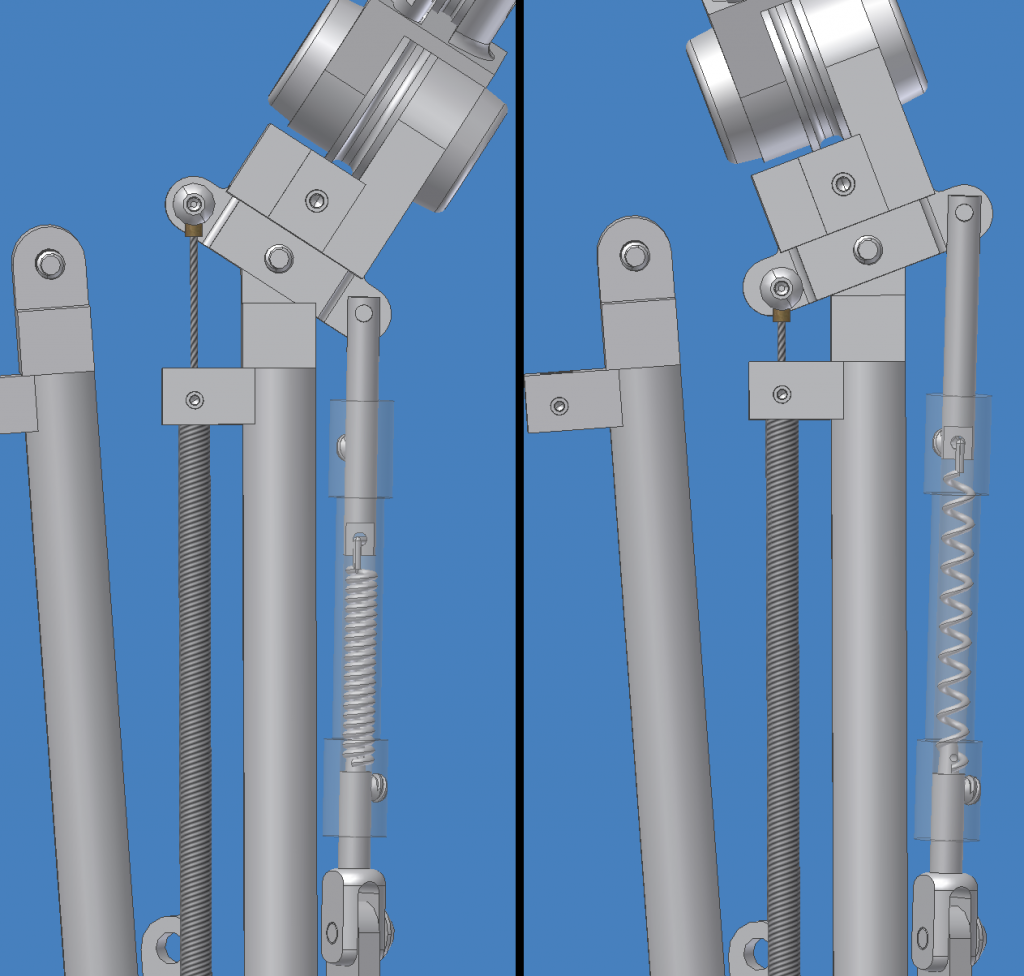
This is my best guess at the paths of the T3 finger cables. These paths will not work with the parts in the blueprints I posted. They need to be modified with various slots, holes, pins, etc.

Finger Control:
Finger%20Controls.PNG

I know it's a busy image, hopefully the different parts are clear enough. Let me know if I need to clarify anything. I may redo it with color coded parts.
Finger Control Cable - Can only provide tension. Pulling this cable causes the finger to curl into a closed position.
Palmar Spring Return - Passive component. Uses a compression spring to push the proximal phalanx to an open position.
Finger Spring Return - Passive component. A compression spring inside each finger joint helps to straighten the finger when the Finger Control Cable is released.
Lumbrical Cable - Can only provide tension. Pulling this cable tips the finger to the side.
Lumbrical Spring Return - Passive component. Uses a tension spring to pull the finger to the side when the Lumbrical Cable is released.

Found Hardware
The Du-Bro 4-40 Solder Rod Ends are fairly easy to get, I bought mine from this website.
DSC02734_zps78d48423.jpg

I haven't been able to find a source of pulleys.

That's all I have for now, I should be able to get some more work done this weekend. If you haven't yet, you should join The Endo Builders Club. There aren't too many regularly posting members, but there is a lot more information, speculation, drawings, and prototypes.
 
Good illustration of cable paths. Good tip on found hardware, specifically Du-Bro 303 clevis. Could also find ball joints and no doubt micro cables with sleeves to fit as well.
 
Last edited:
Above elbow bearing raceway too complicated especially when trying to assemble. Negates the need of an inner humerus lobe or "medial disk".
 

Attachments

  • Medial Elbow Cap.bmp
    576.1 KB · Views: 464
Last edited:

Your message may be considered spam for the following reasons:

If you wish to reply despite these issues, check the box below before replying.
Be aware that malicious compliance may result in more severe penalties.
Back
Top