Newbie Project. Oscillation Overthruster

The piece of the bezel that I call the 'knuckle' assembly has two major components, the 'knuckle' and one of two 'wedges' that are use in the build. The knuckle sports the 'stepped pyramid' detail and is fastened to the orb underneath the cantilevered portion of the orb switch plate support using two 6-32 NC machine screws. The wedge is based on a 30-60-90 triangle and has a tenon that fits in a slot in the knuckle to support the 'face plate.' The face plate 'floats' between the knuckle and the wedge.

knuckle_schematic.jpg wedge_schematic.jpg

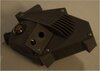
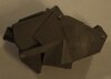
The two following pictures show two views of the knuckle and wedge. The small holes on the top and bottom are drilled and tapped for 2-56 machine screws, for fastening the cover plates. The large hole is drilled and tapped for an 8-32 NC set screw, for securing the wedge.

knuckle1.jpg

knuckle2.jpg

Here the completed knuckle assembly.

knuckle3.jpg

The last picture of this post shows the knuckle assembly fastened to the orb.

orb_knuckle.jpg
 
Agreed Funky. I call for a run of this stainless steel gem. What say you docatonic? Feel up to milling about 10 of these bad boys :)
 
First of all, I'd like to thank everyone for their kind comments. As far as firing up the good ol' milling machine for a production run… I'll have to give it more thought. Although that was my original intent, after each part I milled it became less and less attractive. Plan B was to make resin castings for 'static' versions that would not have all of the electrical innards. However, since you asked, I'll mull the idea over again.

Another component that was modified for the new design is the thumb assembly. It consists of two parts, the thumb piece and the thumb plate.

thumb_schematic.jpg thumbplate_schematic.jpg

The next picture shows the milled thumb piece and thumb plate.

thumb1.jpg

Note that the bottom of the thumb piece has a 'hang nail' (pun intended) that sweeps back at a 30 degree angle. The hang nail slips in a recess milled into the orb giving the appearance that the orb is wrapped around the thumb piece. The thumb piece also has a half-cylinder groove milled at a 45 degree angle. More on this in a bit. Also note that the thumb plate has a large oblong hole in addition to two smaller holes and another medium sized hole. The two small holes are sized for two 2-56 machine screws that fasten the thumb plate to the thumb piece. The medium sized hole is for a 6-32 NC machine screw that attaches the thumb assembly to the orb. The oblong hole and the groove in the thumb piece accommodate the 'tube' that pierces the orb and protrudes into the body of the overthruster. The tube will house three 1.5V button batteries, providing 4.5V to power the LEDs, sound system and a programmable micro-controller.The micro-controller will be used to 'animate' the overthruster when the various switches are pressed.

Here is the thumb assembly.

thumb2.jpg

The next few pictures show different views of the thumb and knuckle assemblies fastened to the orb.

thumb_orb0.jpg thumb_orb1.jpg

thumb_orb2.jpg thumb_orb3.jpg

This will be my last post of the day. If you see where I hail from, you know that there is a ball game that requires mandatory viewing. Roll Tide!
 
This is some kind of serious work! Wow! I want one and I had to look up what it was! (I only saw the film once a long time ago). Now that is a cool looking prop!
 
Well, I really do consider myself a newbie to replica prop building. It's just that I am an anal retentive newbie with O.C.D. ;)

The final components that make up the overthruster bezel are the bridge and nose assembly. The nose assembly has, you guessed it, two pieces: the nose and the second of the two wedges that were discussed earlier.

bridge_scematic.jpg nose_schematic.jpg

I also mentioned in a previous post that there was a 'missing' hole on the bottom cover plate. To add strength to the bezel for this redesign, the bridge and nose pieces were fastened together. To do this I used a lap joint that is fastened by a 2-56 machine screw. The bridge supports both the upper and lower switch plates.

bridge1.jpg bridge2.jpg

The next pictures show the two pieces of the nose assembly prior to and after assembly. The larger of the two holes on each side of the nose are drilled and tapped for 8-42 NC set screws. The smaller holes are drilled and tapped for 2-56 machine screws, for fastening the cover plates. Also, note that the outside lap on the nose piece has a countersunk hole so that the head of the screw securing the bridge to the nose is below the cover plate. The nose helps support the lower switch plate.

nose1.jpg nose2.jpg

nose3.jpg nose4.jpg

The next pictures show the attached bridge and nose assembly. The later has the switch plates attached. I'll discuss the switch plates along with the face plate later.

bridge_nose1.jpg

bridge_nose2.jpg

With all of the bezel pieces complete, the next picture shows the overall layout of the pieces. It also gives a feel for how much 'real estate' is available for the internal electrical/electronic components.

bezel1.jpg
 
Nice Job on this!!

Pic of the original that I took a few years back. You might want the paint/weathering reference.

OVER_cer.jpg
 
Last edited:
Thanks BrundelFly! I have been thinking about how to finish the surfaces. Everything from paint to anodizing. Thanks for the great reference!
 
Absolutely stunning, cant wait to see the final piece ! I'm really digging the wood version as well.

Peanuts
 
Thanks BrundelFly! I have been thinking about how to finish the surfaces. Everything from paint to anodizing. Thanks for the great reference!

You are welcome. Sorry I can't find the other pics. If I do, Ill post. I had pics of the case too someplace.
 
This thread's a little dusty, anymore progress? I was looking forward to finished pics! :)
 
Fantastic build! I'm going to build one of these (styrene) for my dad-in-law for Xmas, I hope it's okay for me to reference your part-out images?

It's been a long time, did it get finished?
 
It's been a while. In the mean time I discovered 3D printers. This one has room for an Arduino Nano, LiPo battery, power converter and the switches & LEDs. I'll post a couple of images. The color of the filament is not very photogenic. More to come.
 

Attachments

  • Top.jpg
    Top.jpg
    19.4 KB · Views: 113
  • Bottom.jpg
    Bottom.jpg
    14.8 KB · Views: 107
It's been a while. In the mean time I discovered 3D printers. This one has room for an Arduino Nano, LiPo battery, power converter and the switches & LEDs. I'll post a couple of images. The color of the filament is not very photogenic. More to come.

Love it. I’ve been wanting a hollow version to power up with some lights and sound forever. Would you sell me a copy or allow me the file for a print?
 
Back
Top