I'd be happy to sell you a copy. The parts take a lot of time to print so, I'll start printing them this weekend. In the mean time I'll post some pictures of the parts before they have been cleaned up so you can see if you're still interested. I'll also list the additional hardware and electrical pieces that I have picked out for the one I am building.
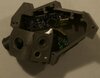
As advertised, the design can hold an Arduino Nano, power converter and LiPo battery (see photo). Components selected for the design are shown in a photo. The 'top plate' has a cavity for a speaker (see photo)
I used Autodesk Fusion 360 for the 3D design. The design consists of 7 components. Below are some screen shots from the software. The slots and rectangular holes will be explained in a later post.
Printer: Anycubic Kossel Linear Plus V2 (a delta style printer)
Slicing Software: Ultimaker Cura 3.6.0
Filament: Rigid.ink PLA 1.75mm Pearl Silver
Nozzle Temperature: 185C
Bed Temperature: 60C
Layer Height: 0.06mm
The images below are the parts straight off the printer with some of the brim removed. The part names also have their print time. Total print time was just shy of 15 hours. Note that the parts are not entirely smooth and require some post-processing. But, also keep in mind that the images are magnified quite a bit (The entire model is only about 3 inches in length). They clean up very nicely.
The degree of clean up is a personal choice. Some like a distressed look, some like it smooth as a baby’s bottom. In any case it’s good to have a diverse selection of sandpaper grits (wet/dry is my choice) and a 1-2-3 block to keep edges crisp. In the images below I’ve only used 220 grit sandpaper. I’ll refine the finish later. The holes for the switches need to be reamed out a bit due to the precision of my 3D printer. A rat-tail file will do the trick. Don’t make the holes too big. The switches are composed of tactile switches and .22 caliber casings that have been trimmed down with a pipe cutter. The hole for the main power switch is sized for a 12mm switch. The one in the image requires a 12-0.75 tap. Images of the assembled mechanical parts are shown below. The next step is to design the electrical components and breadboard. I’ll use an Arduino Uno to prototype before I commit to soldering components to the Arduino Nano.