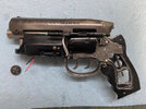
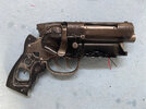
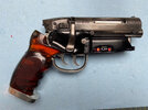
Metal PKD blaster kit from TipTop Workshop / Anders Pedersen - build log

Looking absolutely fantastic wayouteast !! Can't wait to get mine! (I'm #11, so I have a bit to wait haha)
Dumb question as the sanding of the metal parts is what I am most nervous about, worried about accidentally taking too much away haha.
What kind of scotchbrite pads do you mean for the final sanding? Like these? : https://www.amazon.com/3M-Scotch-Brite-Scuff-07445-07447/dp/B00LWTWCKY/ref=sr_1_10?crid=155IX0UFFM28X&keywords=scotch+brite+pad&qid=1683336181&sprefix=scotchbright+pad,aps,111&sr=8-10

Or is there another option I'm not aware of?
Thanks very much! :)

The kit will be worth the wait! The thing with the filing and sanding is to go gently right from the start. It may sound obvious but you can always take a bit more material off if necessary but you can't put material back if you do take too much off! That said, these castings are very high quality out of the box and require very little in the way of cleanup and finishing. Once you've dealt with the very minimal flash and seam lines, you're really smoothing and polishing rather than removing stuff.

Those scotchbrite pads in your link will be fine. I'm cheap and lazy so I tend to use the standard 'general purpose' ones (green) you buy for washing the dishes. I just use the pressure I apply to control their abrasive action - and as they get used they get 'finer' over time, so I don't throw them away until they're practically falling apart!

For the very final smoothing and polishing, though, it's well worth investing in a set of Micro Mesh wet-sanding pads like these. They are of increasingly finer grade from 1500 right up to 12000 and they're invaluable for getting a beautiful smooth polished surface before the final finish. They can be washed and last forever, so they're a very useful investment.

Good luck when you get your kit! I'll look forward to seeing the result!
 
Part 4: Electronics and final assembly

Here’s the final part of this build log - a bit late due to a couple of setbacks with the electronics, entirely due to MY incompetence and NOT the fault of the kit in any way! :)

In the end, though, the problems were a bit of a gift in disguise (as these things so often are) since during the wait for some replacement LEDs I had an idea to tweak the circuit slightly to enable the blaster to have 2 lighting modes (more on that later).

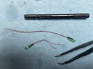
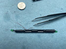
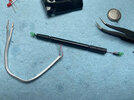
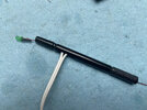
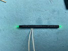
Things started well. The sighting rod was wired up as per the instructions. This was a surprisingly straightforward and easy task, especially with the very fine red and black wire supplied with the kit. I simply soldered the wires to the leads of the LEDs and then trimmed the leads. The wires were twisted together and then fed through the rod from each end. I made sure to leave myself enough slack to make soldering the white wires to the inner ends possible and to leave a bit of slack at the LED ends too. Small lengths of heat shrink were added to insulate the join between the fine wires and the white wires and then the white wires were pushed gently into the slot and a drop of superglue used to hold them in place. A quick final test to ensure the LEDs were working(!) and then the wires at the ends of the rod were then carefully pushed into the rod and the LEDs superglued in place.

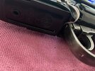
IMG_2421.jpeg IMG_2422.jpeg IMG_2424.jpeg IMG_2425.jpeg IMG_2430.jpeg

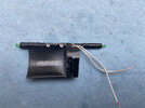
The sighting rod can then be glued and screwed onto the left cylinder cover using the two small phillips head screws supplied. The cover itself is bolted onto the cylinder pivot arm with M3 hex bolts. I used a slightly longer bolt in the top location - 16mm rather than 12mm. The functioning of the cylinder should be checked to ensure everything still works - both the pivoting and the cylinder spin.

IMG_2436.jpeg IMG_2432.jpeg IMG_2433.jpeg


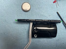
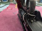
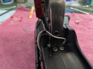
The free ends of the white wires need to be stripped and run through small holes in the back OUTSIDE of the magazine housing in such a way as to lie inside the holes for the magnets inside. They must make contact with the magnets since the magnets are used to conduct the power from the battery in the magazine to the green LEDs. The magnets will be pushed into the holes and secured with a drop of superglue.

I did this with the magazine housing both loosely in place and free as required.

IMG_2461.jpeg IMG_2462.jpeg IMG_2463.jpeg IMG_2465.jpeg

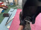
A WORD OF WARNING here. The white wires need to be cut to length. Make sure that you leave them long enough to allow the cylinder to pivot downwards. I had a setback at this stage as I cut them too short. I measured them while the cylinder was closed and after they were attached to the magazine housing this meant there wasn’t enough slack to let the cylinder open. Instead of running through the natural gap between the magazine housing and the cylinder cover at the bottom they entered the gap between the frame too high and forced the magazine housing and the cylinder cover (and cylinder) apart, which impeded the cylinder functionality.

I went through the same steps above and replaced the white wires that I’d cut too short with similar wires from my stash. Re-wiring the sighting rod wasn’t too bad a job. But at the other end I did have to cut the original white wires on the outside of the magazine housing and solder the new wires to the exposed stubs. Luckily, this is completely hidden once the housing and magazine are in place.

At this stage, I experienced another setback involving the two magnets at the front of the magazine housing. I test-fitted them first without pushing them all the way in - i.e. leaving just enough of them proud on the surface to allow me to pull them out with a small pair of pliers. They are a tight fit, and rightly so since they need to be firmly held so they don’t get pulled out by their corresponding magnets when the magazine is removed. All seemed well so I added a drop of superglue to each hole and re-inserted the magnets for what I hoped would be the final time. Horrors! They wouldn’t push all the way in no matter how much pressure I applied. They remained too proud of the surface. They need to be very slightly proud (a fraction of a millimetre) but these were a good 2 millimetres above the surface. Of course, this meant that the magazine was also proud of its proper position when it was inserted.

This presented a problem, since the magnets were now glued into their sockets with not enough of them left visible to grab to remove! To fix this, I had to use a very small rotary burr in my Dremel to grind away the resin on either side of each magnet enough to allow me to yank them out with a pair of needle nose pliers. I enlarged the holes very slightly with another rotary grinding stone and then re-inserted the magnets with 5-minute epoxy all around them to fill the void left by the grinding. Then I left it all to cure overnight just to be safe.

* * *

The following day was one of those days where everything that could go wrong did go wrong!

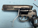
The first thing was to permanently attach the magazine housing in place. This is done with a bolt at the right front which goes through both the magazine housing and the right cylinder cover and into the frame itself. The housing as attached at the front with the large bolt that goes up through the hole at the front, through the front support tube/post and screws into the bottom of the barrel.

Once the housing is attached, it was time for the magazine and the electronics it contains.

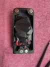
I added the magnets to the magazine itself at this point in the same way as those in the housing, and again the stripped ends of the red and black wires provided have to be inserted through the small drilled holes from the INSIDE to make contact with the base of these magnets.

Watch out for the polarity of the magnets when inserting them so that all the ones in the magazine attract rather than repel their counterparts in the magazine housing.

My next setback was again with a magnet, this time one of the ones in the magazine itself. The red wire slipped out of its hole just as I was inserting the magnet to hold it in place. Of course, inevitably, the superglue decided to cure instantly so I was left with an immovably fixed magnet, almost perfectly flush with the surface and no way of fixing the red wire… which absolutely has to be attached firmly to the magnet. If this should happen to you(!) here's the solution. I used a very thin drill bit in my Dremel to hollow out a space under the magnet - being exceptionally careful not to go all the way through the resin to the visible outside. The wire was then inserted into that hole in such a way as to make contact with the bottom of the magnet and a tiny ball of tinfoil (for added connectivity) was pushed into the hole to wedge it securely in place. This contact was then tested before the wire was superglued in place. I also added a small amount of hot glue at this point to ensure that both the red and the black wires were firmly secured and couldn’t ever be pulled out from their connection to the magnets.

My advice, from the above, is to secure the wires that connect with the magnets in place (with tape or a drop of glue or something) on the outside of the holes before inserting the magnets. :)

At this stage I tested the connection between the magnets by feeding the red and black wires through the hole for the LED in the bottom of the magazine, inserted the magazine and the green LEDs lit, as expected. Hooray! Back on track!

IMG_2438.jpeg IMG_2440.jpeg

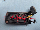
I added the 5 red LEDs and the switch to their sockets in the magazine and soldered them all up using the simple circuit provided by Anders in the assembly instructions. All the LEDs worked fine. I was on a roll. I’d checked the connection between the magnets to the green LEDs so those should illuminate as well when the switch was on. I wrapped the battery in some insulating tape for safety and thought that everything was done.

IMG_2471.jpeg IMG_2475.jpeg IMG_2477.jpeg

I inserted the magazine and flicked the switch. On came the red LEDs. The green LEDs? Nothing. Nada. Zilch. So I checked the magnet connection again on each side with an external battery and leads to power just the green LEDs. Worked perfectly. The magnets were connecting. The red LEDs worked fine. The green LEDs worked fine. But they wouldn’t work together.

Then I had a rush of blood to the head I think. It was late in the day in my defence. I wondered if the battery was depleted. And instead of doing what I should have done and rummaging through the drawer of my workbench for my multimeter, I picked up a variable power supply I had to hand, set it to 3v, de-soldered the battery terminals and connected the power supply.

There was a small ’snap’ as 2 of the red LEDs blew. :eek::mad: Reader, learn from my mistakes! :p

Time for bed and to think about what I'd done.

* * *

I had no 3mm red LEDs in stock, so it would be a few days before replacements arrived. In the meantime I checked the circuit with the multimeter. Of course, there was a voltage drop somewhere in the circuit, from almost 3v at the battery to 1.7v. That voltage was enough to power the red LEDs (which have a forward voltage of about 1.8 - 2v but certainly not enough to light the green LEDs too (they have a forward voltage of around 3.3v). A couple of my solder joints weren’t as clean as they might have been, and that may have been the problem. But with damaged LEDs in the circuit there was no way of knowing for sure.

By the way, I should point out that Dave at TipTop has built this circuit several times, so the fault was entirely with me in this and NOT in any way a problem with the supplied circuit or components, which are top-notch.

I decided to wait for the new LEDs to arrive and then redo the whole thing from scratch, which I did today and all is well as the photos below will attest!

In the meantime, though, I had a thought. In the movie, we never see the green LEDs lit. They were presumably intended to be lit at some point - hence the white wires. But either they failed or Ridley decided against them… and so only the lit red LEDs made it to the final scenes in which the blaster is visible. I wanted to be able to switch the green LEDs separately from the reds so that I could choose whether to have the ‘movie-accurate’ red LEDs only look or the full 7-LED look. So when I re-wired the magazine I made two (actually three if you count adding a resistor) changes from the suggested circuit.

(I did this entirely at my own risk by the way. But after the disaster of a few days before I was feeling quite rash. I had stared into the abyss and nothing now could daunt me! :) I offer this as a suggestion to anyone brave enough to try it!)

  1. I added a second micro slide switch inside the magazine to operate the green LEDs (I have to do this with the magazine removed).
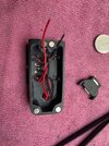
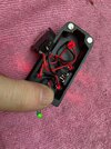
  2. I didn’t connect the wires from the magnets into the rest of the red LED circuit. Instead, I wired them to a second 3v battery with the second switch in between. So there are 2 batteries in the magazine, and two switches (one inside and one outside), the red LEDs are on a single circuit inside the magazine and the green LEDs are on their own separate circuit powered by the second battery in the magazine - the 3v being conducted through the magnets as before.
  3. The red LEDs were a bit bright, I thought, so I experimented with different values of resistor between the original battery and the rest of the circuit, finally deciding on a 470 ohm which dimmed them slightly while still keeping them nice and visible.
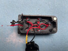
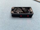
Thankfully, everything worked fine when I tested it - all 5 red LEDs lit when the switch on the side of the magazine was operated, and the internal switch switched on the green LEDs. So I fixed the LEDs in place within the magazine with a few dabs of hot glue, and added electrical tape to insulate all the components where necessary (it’s a very tight squeeze in there!).

IMG_2570.jpeg IMG_2571.jpeg IMG_2591.jpeg IMG_2593.jpeg IMG_2592.jpeg IMG_2588.jpeg

With a sense of relief that the electronics were all done (and an element of crossness at myself for making such a meal out of what should have been a very simple task!) I could complete the final assembly.

The amber grips were attached on each side with a 10mm bolt at the top and a 12 mm bolt at the bottom. Then, finally, the butt plate was attached. You might need to sand the bottom of the grips/grip frame to make sure the combined surface is completely flat so that the butt plate snugs up closely against the bottom of the grips when it’s screwed light. Use a rigid sanding stick or a fine file if you can to get the surface flat. I also found that drilling and tapping the receiving holes in the grip frame slightly deeper and using 16mm rather than 12mm bolts gave me a slightly tighter attachment for the butt plate.

IMG_2595.jpeg IMG_2597.jpeg IMG_2601.jpeg IMG_2603.jpeg IMG_2599.jpeg

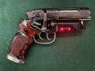
And that’s it! The blaster was fully assembled. And I'm SO delighted with the final result. This will undoubtedly be the centrepiece of my Blade Runner collection. It’s a beautiful piece and a brilliant testament to AndersEFP ’s original modelling and STL files, and to DaveChaos ’s sterling work with moulds and metal over the last 18 months or so to turn them into these wonderful kits.

I want to thank both of them again for their trust and generosity in entrusting me with one of the first of these kits to be produced and to feed back some of my experiences with it - which was wonderfully positive. I had a blast making the blaster. My occasional incompetence aside, it was honestly a dream to build and I absolutely love the final result. I’m sure that those who have put their names down for the kit will be as delighted as I am.

I hope that some of this build log at least has been useful, and thanks for taking the time (and having the patience) to read my ramblings!

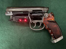
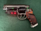
If you haven’t already seen them, there are some final ‘beauty shots’ of the blaster in this thread, which I’ll update with a couple of the shots below of the blaster with lit LEDs.
 
Last edited:
Amazing work! I quite like the idea of separating the circuits for the led sets. I may give that a try as I was a bit worried about the magnet wiring myself. Thanks for another build log, lots of great info for me and others to follow along on their own builds!
 
Lovely job, I'm so glad the kit didn't give you too much trouble seeing the kit finished like this does wonders for my imposter syndrome :lol:
Oh, I'm so glad someone else has that too! :D

You should be hugely proud of your incredible work on this, Dave. It's amazing. I posted some pics over on the Blade Runner Props (PropSummit) Facebook group (even though I'm not a Facebook user normally) and the comments about it - and about TipTop - are really positive. A couple of other RPFers who are in the first batch of the kit are there too.
 
Looks great. Just wondered if you did anything with the Amber grips, did these require polishing or just went on as is?
Thanks! Honestly, they could have gone on as is and been absolutely fine, but I did give both the inner and outer surfaces a really good polish with some Mother's Mag and a soft cloth to preserve the clarity and really make them shine to the max.
 
Part 4: Electronics and final assembly

Here’s the final part of this build log - a bit late due to a couple of setbacks with the electronics, entirely due to MY incompetence and NOT the fault of the kit in any way! :)

In the end, though, the problems were a bit of a gift in disguise (as these things so often are) since during the wait for some replacement LEDs I had an idea to tweak the circuit slightly to enable the blaster to have 2 lighting modes (more on that later).

Things started well. The sighting rod was wired up as per the instructions. This was a surprisingly straightforward and easy task, especially with the very fine red and black wire supplied with the kit. I simply soldered the wires to the leads of the LEDs and then trimmed the leads. The wires were twisted together and then fed through the rod from each end. I made sure to leave myself enough slack to make soldering the white wires to the inner ends possible and to leave a bit of slack at the LED ends too. Small lengths of heat shrink were added to insulate the join between the fine wires and the white wires and then the white wires were pushed gently into the slot and a drop of superglue used to hold them in place. A quick final test to ensure the LEDs were working(!) and then the wires at the ends of the rod were then carefully pushed into the rod and the LEDs superglued in place.

View attachment 1698713 View attachment 1698723 View attachment 1698714 View attachment 1698715 View attachment 1698716

The sighting rod can then be glued and screwed onto the left cylinder cover using the two small phillips head screws supplied. The cover itself is bolted onto the cylinder pivot arm with M3 hex bolts. I used a slightly longer bolt in the top location - 16mm rather than 12mm. The functioning of the cylinder should be checked to ensure everything still works - both the pivoting and the cylinder spin.

View attachment 1698724 View attachment 1698718 View attachment 1698725


The free ends of the white wires need to be stripped and run through small holes in the back OUTSIDE of the magazine housing in such a way as to lie inside the holes for the magnets inside. They must make contact with the magnets since the magnets are used to conduct the power from the battery in the magazine to the green LEDs. The magnets will be pushed into the holes and secured with a drop of superglue.

I did this with the magazine housing both loosely in place and free as required.

View attachment 1698727 View attachment 1698728 View attachment 1698729 View attachment 1698730

A WORD OF WARNING here. The white wires need to be cut to length. Make sure that you leave them long enough to allow the cylinder to pivot downwards. I had a setback at this stage as I cut them too short. I measured them while the cylinder was closed and after they were attached to the magazine housing this meant there wasn’t enough slack to let the cylinder open. Instead of running through the natural gap between the magazine housing and the cylinder cover at the bottom they entered the gap between the frame too high and forced the magazine housing and the cylinder cover (and cylinder) apart, which impeded the cylinder functionality.

I went through the same steps above and replaced the white wires that I’d cut too short with similar wires from my stash. Re-wiring the sighting rod wasn’t too bad a job. But at the other end I did have to cut the original white wires on the outside of the magazine housing and solder the new wires to the exposed stubs. Luckily, this is completely hidden once the housing and magazine are in place.

At this stage, I experienced another setback involving the two magnets at the front of the magazine housing. I test-fitted them first without pushing them all the way in - i.e. leaving just enough of them proud on the surface to allow me to pull them out with a small pair of pliers. They are a tight fit, and rightly so since they need to be firmly held so they don’t get pulled out by their corresponding magnets when the magazine is removed. All seemed well so I added a drop of superglue to each hole and re-inserted the magnets for what I hoped would be the final time. Horrors! They wouldn’t push all the way in no matter how much pressure I applied. They remained too proud of the surface. They need to be very slightly proud (a fraction of a millimetre) but these were a good 2 millimetres above the surface. Of course, this meant that the magazine was also proud of its proper position when it was inserted.

This presented a problem, since the magnets were now glued into their sockets with not enough of them left visible to grab to remove! To fix this, I had to use a very small rotary burr in my Dremel to grind away the resin on either side of each magnet enough to allow me to yank them out with a pair of needle nose pliers. I enlarged the holes very slightly with another rotary grinding stone and then re-inserted the magnets with 5-minute epoxy all around them to fill the void left by the grinding. Then I left it all to cure overnight just to be safe.

* * *

The following day was one of those days where everything that could go wrong did go wrong!

The first thing was to permanently attach the magazine housing in place. This is done with a bolt at the right front which goes through both the magazine housing and the right cylinder cover and into the frame itself. The housing as attached at the front with the large bolt that goes up through the hole at the front, through the front support tube/post and screws into the bottom of the barrel.

Once the housing is attached, it was time for the magazine and the electronics it contains.

I added the magnets to the magazine itself at this point in the same way as those in the housing, and again the stripped ends of the red and black wires provided have to be inserted through the small drilled holes from the INSIDE to make contact with the base of these magnets.

Watch out for the polarity of the magnets when inserting them so that all the ones in the magazine attract rather than repel their counterparts in the magazine housing.

My next setback was again with a magnet, this time one of the ones in the magazine itself. The red wire slipped out of its hole just as I was inserting the magnet to hold it in place. Of course, inevitably, the superglue decided to cure instantly so I was left with an immovably fixed magnet, almost perfectly flush with the surface and no way of fixing the red wire… which absolutely has to be attached firmly to the magnet. If this should happen to you(!) here's the solution. I used a very thin drill bit in my Dremel to hollow out a space under the magnet - being exceptionally careful not to go all the way through the resin to the visible outside. The wire was then inserted into that hole in such a way as to make contact with the bottom of the magnet and a tiny ball of tinfoil (for added connectivity) was pushed into the hole to wedge it securely in place. This contact was then tested before the wire was superglued in place. I also added a small amount of hot glue at this point to ensure that both the red and the black wires were firmly secured and couldn’t ever be pulled out from their connection to the magnets.

My advice, from the above, is to secure the wires that connect with the magnets in place (with tape or a drop of glue or something) on the outside of the holes before inserting the magnets. :)

At this stage I tested the connection between the magnets by feeding the red and black wires through the hole for the LED in the bottom of the magazine, inserted the magazine and the green LEDs lit, as expected. Hooray! Back on track!

View attachment 1698735 View attachment 1698726

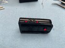
I added the 5 red LEDs and the switch to their sockets in the magazine and soldered them all up using the simple circuit provided by Anders in the assembly instructions. All the LEDs worked fine. I was on a roll. I’d checked the connection between the magnets to the green LEDs so those should illuminate as well when the switch was on. I wrapped the battery in some insulating tape for safety and thought that everything was done.

View attachment 1698741 View attachment 1698742 View attachment 1698743

I inserted the magazine and flicked the switch. On came the red LEDs. The green LEDs? Nothing. Nada. Zilch. So I checked the magnet connection again on each side with an external battery and leads to power just the green LEDs. Worked perfectly. The magnets were connecting. The red LEDs worked fine. The green LEDs worked fine. But they wouldn’t work together.

Then I had a rush of blood to the head I think. It was late in the day in my defence. I wondered if the battery was depleted. And instead of doing what I should have done and rummaging through the drawer of my workbench for my multimeter, I picked up a variable power supply I had to hand, set it to 3v, de-soldered the battery terminals and connected the power supply.

There was a small ’snap’ as 2 of the red LEDs blew. :eek::mad: Reader, learn from my mistakes! :p

Time for bed and to think about what I'd done.

* * *

I had no 3mm red LEDs in stock, so it would be a few days before replacements arrived. In the meantime I checked the circuit with the multimeter. Of course, there was a voltage drop somewhere in the circuit, from almost 3v at the battery to 1.7v. That voltage was enough to power the red LEDs (which have a forward voltage of about 1.8 - 2v but certainly not enough to light the green LEDs too (they have a forward voltage of around 3.3v). A couple of my solder joints weren’t as clean as they might have been, and that may have been the problem. But with damaged LEDs in the circuit there was no way of knowing for sure.

By the way, I should point out that Dave at TipTop has built this circuit several times, so the fault was entirely with me in this and NOT in any way a problem with the supplied circuit or components, which are top-notch.

I decided to wait for the new LEDs to arrive and then redo the whole thing from scratch, which I did today and all is well as the photos below will attest!

In the meantime, though, I had a thought. In the movie, we never see the green LEDs lit. They were presumably intended to be lit at some point - hence the white wires. But either they failed or Ridley decided against them… and so only the lit red LEDs made it to the final scenes in which the blaster is visible. I wanted to be able to switch the green LEDs separately from the reds so that I could choose whether to have the ‘movie-accurate’ red LEDs only look or the full 7-LED look. So when I re-wired the magazine I made two (actually three if you count adding a resistor) changes from the suggested circuit.

(I did this entirely at my own risk by the way. But after the disaster of a few days before I was feeling quite rash. I had stared into the abyss and nothing now could daunt me! :) I offer this as a suggestion to anyone brave enough to try it!)

  1. I added a second micro slide switch inside the magazine to operate the green LEDs (I have to do this with the magazine removed).
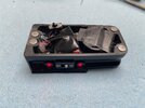
  2. I didn’t connect the wires from the magnets into the rest of the red LED circuit. Instead, I wired them to a second 3v battery with the second switch in between. So there are 2 batteries in the magazine, and two switches (one inside and one outside), the red LEDs are on a single circuit inside the magazine and the green LEDs are on their own separate circuit powered by the second battery in the magazine - the 3v being conducted through the magnets as before.
  3. The red LEDs were a bit bright, I thought, so I experimented with different values of resistor between the original battery and the rest of the circuit, finally deciding on a 470 ohm which dimmed them slightly while still keeping them nice and visible.
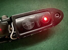
Thankfully, everything worked fine when I tested it - all 5 red LEDs lit when the switch on the side of the magazine was operated, and the internal switch switched on the green LEDs. So I fixed the LEDs in place within the magazine with a few dabs of hot glue, and added electrical tape to insulate all the components where necessary (it’s a very tight squeeze in there!).

View attachment 1698744 View attachment 1698749 View attachment 1698752 View attachment 1698753 View attachment 1698754 View attachment 1698750

With a sense of relief that the electronics were all done (and an element of crossness at myself for making such a meal out of what should have been a very simple task!) I could complete the final assembly.

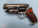
The amber grips were attached on each side with a 10mm bolt at the top and a 12 mm bolt at the bottom. Then, finally, the butt plate was attached. You might need to sand the bottom of the grips/grip frame to make sure the combined surface is completely flat so that the butt plate snugs up closely against the bottom of the grips when it’s screwed light. Use a rigid sanding stick or a fine file if you can to get the surface flat. I also found that drilling and tapping the receiving holes in the grip frame slightly deeper and using 16mm rather than 12mm bolts gave me a slightly tighter attachment for the butt plate.

View attachment 1698755 View attachment 1698756 View attachment 1698759 View attachment 1698758 View attachment 1698757

And that’s it! The blaster was fully assembled. And I'm SO delighted with the final result. This will undoubtedly be the centrepiece of my Blade Runner collection. It’s a beautiful piece and a brilliant testament to AndersEFP ’s original modelling and STL files, and to DaveChaos ’s sterling work with moulds and metal over the last 18 months or so to turn them into these wonderful kits.

I want to thank both of them again for their trust and generosity in entrusting me with one of the first of these kits to be produced and to feed back some of my experiences with it - which was wonderfully positive. I had a blast making the blaster. My occasional incompetence aside, it was honestly a dream to build and I absolutely love the final result. I’m sure that those who have put their names down for the kit will be as delighted as I am.

I hope that some of this build log at least has been useful, and thanks for taking the time (and having the patience) to read my ramblings!

If you haven’t already seen them, there are some final ‘beauty shots’ of the blaster in this thread, which I’ll update with a couple of the shots below of the blaster with lit LEDs.
This looks stunning. When I can get my hands on a kit I hope I can do it justice. Your tremendous build log will go along way in helping me and everyone out.
 
wayouteast, You mentioned that you were going to "try" to match the paint on the cylinder to the finish of the gun. The photo here looks bang on! What did you end up panting it with?
First primed with Tamiya fine surface primer. Then a gloss black base coat (rattle can). I scuffed that in an irregular way to give a sort of ‘mottled’ satin to gloss surface and then airbrushed AK Interactive X-treme Metal ‘gunmetal’ in thin coats until it matched the tone and colour of the treated frame parts. Once that had cured fully I gave it a light weathering pass with black and burnt umber acrylic applied with a sponge and then very gently scuffed back with 0000 wire wool using directional strokes to look like natural faint wear and scratches. The final touch was some highlighting on the edges with silver run n buff.
 
Last edited:
Top to bottom, this is an absolute masterpiece. Congratulations on a bar-setting build and finish. I can't wait for Dave to notify me about my parts request to upgrade the resin-printed equivalent on mine!
 

Your message may be considered spam for the following reasons:

If you wish to reply despite these issues, check the box below before replying.
Be aware that malicious compliance may result in more severe penalties.
Back
Top