There have been a few developments I haven't mentioned yet.
The first is I finally found a LCD panel that both should be a perfect fit, and something I can actually drive with an image!
The screen I did want to use only accepts DSI MIPI input, and while in theory the Raspberry Pi can output that signal, the developers an "open source" micro controller, decided to keep the code so that only the two screens they sell can work. All others need to dig into the root coding, and so far after many years I have yet to see a single person implement it successfully.
SPI is a much slower interface, but is also much more compatible, and can be driven by something as simple as an arduino.
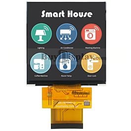
The SPI display I found a 4"x4" LCD that is 480x480 pixels, enough to display the text and basic graphics needed for a Pip-Boy.
 www.buydisplay.com
It should also be much brighter than the VR tweaked screen I was using.
www.buydisplay.com
It should also be much brighter than the VR tweaked screen I was using.
I ordered a couple of them nearly a month ago, but they are on the slow boat from china, so I have no idea when they will arrive.
At the same time I spent over $350 on SparkFun in order to get new development and sensor boards to try to revamp this project. This way I don't have to breadboard every tiny sub-circuit.
I ordered the SparkFun MicroMod with display carrier board. This has a SPI display on board, and I am painfully learning how to get the graphics library to display stuff. So far, I have it displaying just the boot screen text. I am not sure if I want to use the Artemis board or the RP2040 board to drive the thing. The RP2040 is supposed to be much faster, but I am not very familiar with Python, and am much better at coding in C++.
I also ordered the following:
FM Tuner board
Pulse Oximeter and Heart Rate Sensor
Battery charger/ Fuel Gauge
GPIO expander
IR thermal sensor
Motor Driver
9 degree of freedom IMU
A bunch of Qwiic breakouts, splitters and cables
Regarding the question on metal 3D printing: Metal 3D printing is still very expensive. It also still requires lots of supports that have to be manually ground away. It is far from being practical to print out a metal pip-boy body (at least with all the internal structures in place)
However, within the next few months I will have access to a Fuse 1 3D printer. That will make it so that printing out the entire set of parts will drop from $350 to $115. It will at least mean if I need to make any more mechanical changes, they won't be so costly to prototype. The catch is it only makes parts in a dark grey nylon, and some of the parts on the Pip-Boy do need to be white, but there is always paint for that.
All that said, this is still a back burner project for me. I have a few other functional props which may still come first. I need to finish the Dosimeter. I ran into a road block where the MSP430 is very difficult to program without a carrier board, so in-field updates were nearly impossible. I may even report the whole thing over to a more easy to use microcontroller, and simplify some aspects of the design.
I am otherwise spending my free time on Leatherman Tool accessories (and video games). The tool parts sell and help fun the rest of my hobbies. Including ordering all those SparkFun boards. To that end I will soon be revamping my website to be a store, showcase, and blog all in one.
The first is I finally found a LCD panel that both should be a perfect fit, and something I can actually drive with an image!
The screen I did want to use only accepts DSI MIPI input, and while in theory the Raspberry Pi can output that signal, the developers an "open source" micro controller, decided to keep the code so that only the two screens they sell can work. All others need to dig into the root coding, and so far after many years I have yet to see a single person implement it successfully.
SPI is a much slower interface, but is also much more compatible, and can be driven by something as simple as an arduino.
The SPI display I found a 4"x4" LCD that is 480x480 pixels, enough to display the text and basic graphics needed for a Pip-Boy.
4 inch TFT LCD Display 480x480 Pixel w/MIPI Interface for IoT devices
ER-TFT040-2 is 4 inch color tft lcd display in 480x480 pixels with 4-wire SPI+RGB,4-wire SPI+MIPI interface for IoT devices,landscape mode is available.
www.buydisplay.com
I ordered a couple of them nearly a month ago, but they are on the slow boat from china, so I have no idea when they will arrive.
At the same time I spent over $350 on SparkFun in order to get new development and sensor boards to try to revamp this project. This way I don't have to breadboard every tiny sub-circuit.
I ordered the SparkFun MicroMod with display carrier board. This has a SPI display on board, and I am painfully learning how to get the graphics library to display stuff. So far, I have it displaying just the boot screen text. I am not sure if I want to use the Artemis board or the RP2040 board to drive the thing. The RP2040 is supposed to be much faster, but I am not very familiar with Python, and am much better at coding in C++.
I also ordered the following:
FM Tuner board
Pulse Oximeter and Heart Rate Sensor
Battery charger/ Fuel Gauge
GPIO expander
IR thermal sensor
Motor Driver
9 degree of freedom IMU
A bunch of Qwiic breakouts, splitters and cables
Regarding the question on metal 3D printing: Metal 3D printing is still very expensive. It also still requires lots of supports that have to be manually ground away. It is far from being practical to print out a metal pip-boy body (at least with all the internal structures in place)
However, within the next few months I will have access to a Fuse 1 3D printer. That will make it so that printing out the entire set of parts will drop from $350 to $115. It will at least mean if I need to make any more mechanical changes, they won't be so costly to prototype. The catch is it only makes parts in a dark grey nylon, and some of the parts on the Pip-Boy do need to be white, but there is always paint for that.
All that said, this is still a back burner project for me. I have a few other functional props which may still come first. I need to finish the Dosimeter. I ran into a road block where the MSP430 is very difficult to program without a carrier board, so in-field updates were nearly impossible. I may even report the whole thing over to a more easy to use microcontroller, and simplify some aspects of the design.
I am otherwise spending my free time on Leatherman Tool accessories (and video games). The tool parts sell and help fun the rest of my hobbies. Including ordering all those SparkFun boards. To that end I will soon be revamping my website to be a store, showcase, and blog all in one.
") As always, standing by and looking forward to whatever you do whenever you do it. You never disappoint. It is always, at the very least, interesting and educational.
As always, standing by and looking forward to whatever you do whenever you do it. You never disappoint. It is always, at the very least, interesting and educational.