As I alluded to in another thread recently, this particular prop has always been an obsession of mine and I have been working on my own parametric 3D model on and off for nearly 3 years. I have amassed a fairly large collection of reference photos of both the hero prop and the various stung props. So to the best of my abilities I have been using perspective matching photogrammetric techniques within SolidWorks to align my model to reference photos.

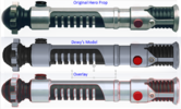
Comparison 1:

Comparison 2:

I scratched my brain for a month over how a machinist would logically manufacture the emitter with the wonky geometry we see on the hero prop. It turns out it is incredibly easy:

Finally after A LOT of time in Solidworks I decided I was ready to move forward with prototyping. My interests lie more in replicating the prop than the fictional weapon itself. In that regard I decided to 3D print not just my hero model, but also a featureless stunt model to recreate these props:

So these beauties are hot off the 3D printer:


Now begins the long and arduous task of turning my 3D models into detailed engineering drawings...
Comparison 1:
Comparison 2:
I scratched my brain for a month over how a machinist would logically manufacture the emitter with the wonky geometry we see on the hero prop. It turns out it is incredibly easy:
Finally after A LOT of time in Solidworks I decided I was ready to move forward with prototyping. My interests lie more in replicating the prop than the fictional weapon itself. In that regard I decided to 3D print not just my hero model, but also a featureless stunt model to recreate these props:
So these beauties are hot off the 3D printer:
Now begins the long and arduous task of turning my 3D models into detailed engineering drawings...