Well after nearly 6 months of research, I think I've finally hit upon that above part. It looks a lot like an insert for a drive shaft coupler commonly used on RC model boats, and appears to mostly be sold in Europe. I've ordered a couple of different ones to try out.
You are using an out of date browser. It may not display this or other websites correctly.
You should upgrade or use an alternative browser.
You should upgrade or use an alternative browser.
Portable Automated Somnacin IntraVenous (PASIV) device, "INCEPTION" *spoliers?*
- Thread starter Chronos
- Start date

Received the printed Upper vacuum pump housings last week and spent the weekend sanding and painting them. They turned out fantastic, and I can assemble the upper "ring" of pumps and timers now. Since the lower pump ran a bit large, the upper ring is large too, and I am pretty constrained on the North and South IV reels fitting in, but I still think they can fit. The bigger issue is that I'll need to widen the circle cutout in the base plate to accommodate the CNC'd foundation, and that might not leave much room for the corner trap door and "L" shaped part. At least I have a solid design and worst case I'll need to reprint these 4 pumps and spend a few more days refinishing.


Things are just staged here, so parts aren't completely lined up. I'm not sure yet how I want to affix these. I could just independently secure each pump into the foundation, and also do the same with the timer/reel assemblies. But it just feels like the entire ring should be attached together as one. The acrylic vac pump cylinders stick out a little farther than the bottom of the printed parts (just like the lower pumps) because that excess will be glued in and secured to the metal foundation around it.
Next up: working on the Spare Vial Holder that goes up in the top left corner of the lower section, and more and more research and experimentation on the reel mechanics.
I did receive one of my coupler inserts to try: DH022 here: Couplings
The size is pretty close, but the collar is hex, not round, and the splines on the "gear" part are a bit too low profile to actually hook the timing belt. It could probably look the part but wouldn't be functional. We'll see how the others work.
Last edited:
I actually got two, with one in a finer detail plastic. It was translucent so I hit it with some glossy white, and I do like it for other reasons. It really shows more crisp lines and you can see the detail of the grooves better. But the flat one is more screen accurate.

Maybe I rough up the surface details of this one and leave the grooves alone?
Maybe I rough up the surface details of this one and leave the grooves alone?
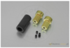
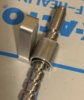
These just arrived: FLEXI shaft coupler 12, 4/4,2
Round collars, a set screw, and they have much better traction to use as gears.

I have a prototype reel on the way and design for the retention plates is in progress. Hopefully I can get a single fully assembled first reel within the month.
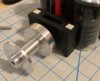
Here it is attached to the drive shaft and one of the unfinished test timers:

Round collars, a set screw, and they have much better traction to use as gears.
I have a prototype reel on the way and design for the retention plates is in progress. Hopefully I can get a single fully assembled first reel within the month.
Here it is attached to the drive shaft and one of the unfinished test timers:
Last edited:
Inching closer this weekend. I have a couple of prototype reel components in the works, hope to be able to show those soon and get the first proof-of-concept reel working. Still unsure if I'll be able to actually cram the motors in, but at least it'll look the part. I cut out the rest of the spots on the lower base plate for them to fit, and starting building the skeletal frame underneath the plate to stabilize and secure it. The biggest thing is I got some strong mounting adhesive and assembled the upper ring into a single part.
I used some more (temporary) adhesive to mount it into the lid and see how it works. It looks great, the case fully closes, and as expected, the lower pump neatly tucks into the upper pump ring. Long term: the upper ring will be mounted into a CNC'd foundation that (most likely) will be secured into the lid with Pro Poxy 20. Everything else so far: the Spare Vial Holder, the Battery Case, the "L"-shaped parts, and trap door are all paper mockups while I figure out scaling and fit. I also started planning for the base plate perimeter and lined the areas with tape to make sure none of my parts will overlap with it. In scale, I still think my IV tubing is too wide, but haven't found a replacement yet.
My biggest concern right now is upper fit. Since the lower pump is a bit large, so too must the upper ring be oversized, which pushes out the foundation circle, which pushes out the outer baseplate cut, which eats into the space available for: the North and South reels, the trap door, the upper "L"-shape, and I may simply not have room for things like mounting the upper Clippard pneumatics. Hopefully I won't need to remake anything major, but there's still a lot that could go wrong. But right now the acrylic chambers for the pumps are touching the edge of the base plate, and they absolutely should not be.
Spare Vial Holder should be finished this week. Fingers crossed that I got the cutout right for the hinge to fold into.
Anyone looking to build one, a Zero Halliburton P5-SI has appeared on eBay: https://www.ebay.com/itm/Vtg-Zero-Halliburton-Aluminum-Briefcase-18-x-13-x-5-Hidden-Combo-Laptop-Attache/223513785949
These are long out of production and don't come up that often, and at the cheapest price I've ever seen one.
These are long out of production and don't come up that often, and at the cheapest price I've ever seen one.
I finally found some tubing I'm happy with. My previous stuff came from a medical supply company and was intended for catheter patients. It's 4mm OD and a smooth clear plastic. It was a bit too wide, didn't coil up very easily, and when it did, over time would retain it's shape. So even when you unspool it, it would retain the curls.
The new stuff is much nicer.
uxcell Silicone Tube 1mm ID X 2mm OD 32.8' Flexible Silicone Rubber Tubing Water Air Hose Pipe Transparent for Pump Transfer
https://www.amazon.com/gp/product/B01MXLNS5K
It's silicone, so it is a little bit stretchy, but it has the proper weight so it will drape out of the case the way it should, and it won't retain curls. It's also a little cloudy instead of being a totally clear. It's small enough that I can actually double up the tubes in the screen accurate way (infusion + return tubes) in a single IV adapter. What you see here is 2mm OD, but I've also ordered some 3mm to compare.

I'm going to keep using the 4mm plastic tubing for the valve switches and pneumatic cylinders though, where a wider OD is needed and rigidity is actually important.
In the next couple of weeks I should have the Spare Vial Holder and the first few fabricated metal parts in hand. A lot of design hurdles have been cleared and I now think the remainder of the case will take closer to 3 months, not 6 like I thought.
The new stuff is much nicer.
uxcell Silicone Tube 1mm ID X 2mm OD 32.8' Flexible Silicone Rubber Tubing Water Air Hose Pipe Transparent for Pump Transfer
https://www.amazon.com/gp/product/B01MXLNS5K
It's silicone, so it is a little bit stretchy, but it has the proper weight so it will drape out of the case the way it should, and it won't retain curls. It's also a little cloudy instead of being a totally clear. It's small enough that I can actually double up the tubes in the screen accurate way (infusion + return tubes) in a single IV adapter. What you see here is 2mm OD, but I've also ordered some 3mm to compare.
I'm going to keep using the 4mm plastic tubing for the valve switches and pneumatic cylinders though, where a wider OD is needed and rigidity is actually important.
In the next couple of weeks I should have the Spare Vial Holder and the first few fabricated metal parts in hand. A lot of design hurdles have been cleared and I now think the remainder of the case will take closer to 3 months, not 6 like I thought.

CNC'd metal parts should start arriving next week. It's going to be a busy month of assembly. I got a few more small parts in today too, the correct support pins for the reels, the spacers that will act as the shuttles for the line carriages, and the 3mm tubing. Even side by side, I'm still undecided on the 2mm or 3mm. I need more time to think on it.
The Spare Vial Holder is finished. This didn't take long to sand to 3000 and paint. There are only minor differences in the original and mine, and the vials are a perfect fit*. I have drilled mounting holes so this can attach to the base plate properly.


*Well. The slots are calibrated exactly for the size of the glass, but the screw caps are just barely (<0.5mm) wider, but enough that trying to force them down and into the 'cups' was causing the walls to bend, and basically they wouldn't go all the way. So I decided rather than file away some material from the holder slots, to take just these 4 vials and Dremel down the diameter of their caps to be equal to the diameter of the glass, so there's a nice snug fit.
The Spare Vial Holder is finished. This didn't take long to sand to 3000 and paint. There are only minor differences in the original and mine, and the vials are a perfect fit*. I have drilled mounting holes so this can attach to the base plate properly.
*Well. The slots are calibrated exactly for the size of the glass, but the screw caps are just barely (<0.5mm) wider, but enough that trying to force them down and into the 'cups' was causing the walls to bend, and basically they wouldn't go all the way. So I decided rather than file away some material from the holder slots, to take just these 4 vials and Dremel down the diameter of their caps to be equal to the diameter of the glass, so there's a nice snug fit.
Andimartin
New Member
I don't know whether these help you or not. I saw the case or a version of the case at an exhibit a couple of years ago now in London and took a few pictures just found them when going through some of my old files. Wanted to make this case myself but don't have the time at the moment.


Thanks! Yeah more reference always helps!
Wow, already I can spot a few things I couldn't before:
- The drive shaft gear has a set screw. So it's probably not threaded.
- The base plate perimeter is cut where the spare vial holder is, the holder doesn't sit on top of the perimeter.
- The forward Clippard cylinder sits on the inner perimeter, but the rear one sits just outside of it. That seems like a design/build oversight.
- Clearest shot yet of the top of the Battery Case. I'm designing that part now so that's a big help just in time.
- Best shot yet of the drive shaft inserting into the timer. Still can't see that it's actually hooked up to any kind of motor yet.
- There's a vertical downward clamp type piece on the back of the line carriage shuttle. So far I've just designed for the carriage and the shuttle, and was wondering how they kept from spinning around. I wonder if they actually put a pawl inside it to make it move.
I'm using a Penn reel part 42-975 for my drive shaft, and the 3/8"L x 1/4"OD x 0.198"ID slotted unthreaded spacer from McMaster-Carr is a perfect fit for it.
Last edited:
Andimartin
New Member
Glad they will be of some use to you. Good luck with the project. This is the only other photo i had. Wish i took more than a 50mm lens with me that day.

Nice. That last pic has the clearest view yet of the carriage guide piece underneath the drive shaft, and how it connects with the timer. I'm currently trying to work out the entire reel assembly: timer, mounts, spool, scoop/well, pins, shaft, and retention plate. It's somehow squeeze it into available space since my central pump runs a bit large.
I love on these hi-res shots where you can actually see the 3D print lines on some of the parts of the hero prop (battery cases, spare vial holder) as well as the machining marks on various bits like the tubing carriages.
I love on these hi-res shots where you can actually see the 3D print lines on some of the parts of the hero prop (battery cases, spare vial holder) as well as the machining marks on various bits like the tubing carriages.
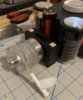
Huge thanks to RPF member linein for the metal "rotor" piece. The pattern and finish is absolutely spot-on.
You will notice that the center dial appears small in this compared to the original.. actually I'm pretty sure the dial is correct, but I've scaled the rotor and ring of timers/pumps larger than actual, so it would cleanly fit over the lower pump in the closed case. Yay for cascading scaling problems. I still think I can push things out a little further and make it all fit and nothing will have to be remade.
I think I will need the upper "foundation" metal support pieces in place before this can permanently be mounted, but it sure feels great to see both the printed and machined parts coming together.
The following Reel parts should be coming in next:
- retention plates
- spool (one for test)
- spool wells/side mounts
- tubing carriages
This weekend I remade all of my IV tubing using the 3mm uxcell silicone, around 6.5ft per pump, with double tubes. I may end up shortening it depending on how much fits on the spool, but better to start out with too much. The PASIV "manual" states 4ft per pump, which doesn't seem long enough really vs what we see on film.
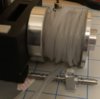
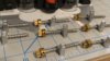
Clippard cylinder mounts came in today:

As did the tubing carriages. I'll need to make the back piece that folds under it, and then attach them to the shuttles:

I got a little scared because I neglected to ensure that the 3mm double tubing would actually fit in the holes, so I completely lucked out on these. They fit perfectly with not a micron to spare, and smoothly move back and forth. I still need to make the back part of the carriages, but the hard part is solved.

Huge thanks to RPF member Makergeeek for the 3D designs for both of these.


As did the tubing carriages. I'll need to make the back piece that folds under it, and then attach them to the shuttles:
I got a little scared because I neglected to ensure that the 3mm double tubing would actually fit in the holes, so I completely lucked out on these. They fit perfectly with not a micron to spare, and smoothly move back and forth. I still need to make the back part of the carriages, but the hard part is solved.
Huge thanks to RPF member Makergeeek for the 3D designs for both of these.
Got all the tubing carriages built. Also I decided the shaft gear was a bit too long so I cut them down a bit.
Some printed prototypes of the reel retention plates and spool wheel should be here in a a day or two, so I can make final adjustments before metal production.
It won’t be long before the only things left will be assembly and electronics.
Some printed prototypes of the reel retention plates and spool wheel should be here in a a day or two, so I can make final adjustments before metal production.
It won’t be long before the only things left will be assembly and electronics.
Attachments
Similar threads
- Replies
- 3
- Views
- 433
- Replies
- 312
- Views
- 50,600
- Replies
- 367
- Views
- 53,387
- Replies
- 301
- Views
- 83,140
- Replies
- 47
- Views
- 7,989