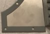
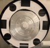
Portable Automated Somnacin IntraVenous (PASIV) device, "INCEPTION" *spoliers?*

Thanks. I've concluded that your photos are definitely a different prop than the earlier ones found on Flickr. Yours is probably one used more on screen, as it has the activation button collar recessed below the pump housing as opposed to sitting on top. Also the timers on yours don't have a separate top cover piece, and the screens are clearly not green LCDs but look like they might actually be capable of the red LED matrix we see on screen. There's a few other tiny details too to show it's different, but overall both sets of photos are a huge help.
 
Got some printed prototypes of the spool well and end plates. Well looks good, end plate is mostly right. The drive shaft hole is a bit too high though, which causes the carriage to hang so high up that it never even touches the well mount at all. So moving this hole down a bit before going full metal production on these.

Otherwise, things are a great fit and this gives me final guidance on how high to mount the base plates.
 

Attachments

  • D3B6CC36-8FDD-42AB-872F-25845D2A64AD.jpeg
    D3B6CC36-8FDD-42AB-872F-25845D2A64AD.jpeg
    1.8 MB · Views: 202
  • FFF41159-1992-4072-B4EA-B4D6330F3A20.jpeg
    FFF41159-1992-4072-B4EA-B4D6330F3A20.jpeg
    1.5 MB · Views: 219
It's been a little while. I've still been calculating the machined pieces since I'm at the critical stage where things just might not all fit together. Making lots of tweaks to the various tubing reel parts. Good news is the lower pump foundation is in production and in a couple of weeks I should have that together, and then I can pull the trigger on the final production versions of the reel spools, scoops, and retention plates. There's just so much to do.

But this weekend I did the Battery Cases finished (Thank you again Futurescape 3D). They hold 10 AA's each and to my eye the scale is spot-on.

bWuxG0Z.jpg


iqRnCNE.png


hbXBWmt.png


5elabH2.png
 
All machined reel parts have been ordered (spools, wells, retention plates) as well as the lower foundation that surrounds the pumps. ETA ~3 weeks on those parts.

Still left to be machined is the upper (lid) metal foundation that the upper pump/timer "ring" fits into. This one is going to be tricky and I'll need to carefully trace out the exact footprint of the upper pump assembly to get the sockets in the right place.

Also the upper and lower "base plates" will need to be milled. So far in all my photos you've just seen some thin sheet metal I've cut as needed as I add the other components, to give myself a rough idea on what the final shape should be. Once everything has been fitted, I'll finalize the design of the base plates, including screw holes, and get those made up. Hopefully that will include the 2 trap doors as well. My plan is to put any real world electronic switches behind those doors.

On the 3D printing front, only 2 things remain: the pair of white "L" shapes, which are being designed right now, and the base plate perimeters. The perimeters are pretty custom curved to the size and shape of the P5-SI, so my guess is they were also printed on the hero prop. I'll be doing these in sections and attaching them to the final base plates, which will probably be 1/8" thick.

Once I have 100% of the parts and only assembly remains, I'll focus exclusively on electronics.
 
Final reel wells and end plates are in, and spools should be arriving today. Then finally I can wrap up all this silicone tubing I've had laying around my work bench for months. The lower metal foundation also came in... but unfortunately was just 0.3" too small for my pump housing to fit into. I've been slowly and carefully machining away at it to get it to a perfect fit, and it's nearly there.

But today I wanted to show that one of the final printed parts has arrived: the "L" shapes:

Qri9lVt.jpg


OTKAjQn.jpg


S7m7phH.jpg


This leaves only the following to be made:
- Machined foundation for upper pumps (figuring out this shape is proving incredibly hard)
- Base plates (machined)
- Base plate perimeters (printed)

From here on until final assembly, I'm going to hold off on posting pictures of the entire build until the final reveal. I'll still update with part level progress.
 
After a few months off, I’m back on this until it’s finished. At least the physical build. The electronics will take awhile longer to figure out.

Thanks to Douglas again for help figuring out the base plate design for the lower section and creating the CAD files. These pass the cardboard mockup test. Next is a printed plastic test, then machining.

Also based on these dimensions, the perimeters for the base plates are also in the design phase.

Upper section plates and perimeters won’t be difficult designs at all, save for figuring out exactly how large that big circle should be given my overscaled upper pumps.
 

Attachments

  • 4CBD48C7-2497-4207-94C9-5FCF56AD2C0B.png
    4CBD48C7-2497-4207-94C9-5FCF56AD2C0B.png
    282 KB · Views: 94
  • DA0FB94C-B836-49A9-8A3E-D8C47B29DCD4.png
    DA0FB94C-B836-49A9-8A3E-D8C47B29DCD4.png
    308.5 KB · Views: 101
Designs are nearly final for the base plates and printed prototypes are in production. These will be 1/16" brushed aluminum. Printed plastic perimeters also almost ready.

The circular cutout in the upper plates will have to be at least 12.25" diameter.

That will just leave the upper pump foundation, a larger circular "socket" piece that the upper vacuum pumps and vials fit into. That's still going to be the hardest thing to design.

Then onto assembly.

Electronics are going to be another project.
 
Screens are installed in timers
 

Attachments

  • 2C2D534C-7EC4-4FDD-8272-EC8A13970BF2.jpeg
    2C2D534C-7EC4-4FDD-8272-EC8A13970BF2.jpeg
    923.3 KB · Views: 123
  • 9F64201A-1702-4447-98B4-3844CE4DE29C.jpeg
    9F64201A-1702-4447-98B4-3844CE4DE29C.jpeg
    329.4 KB · Views: 97
Base plate and perimeter designs are final and parts are on the way. ETA 10 days. Then the only part left to solve is the upper foundation.

If anyone is good with electronics and would like to help with the illuminated toggle switch, timers, and/or the sound effect, please contact me.
 
Big week! Lower base plates and all perimeters are in. Spent the weekend sanding and painting perimeters and started drilling holes in the plates. Taking a little time because they are steel. Had to buy a whole new set of special drill bits. Should get the upper base plates in a week.

I also finally got to permanently install the lower metal foundation in the case using a stick of Pro Poxy 20 steel-reinforced putty. That is never coming out. Not ready to show that yet, saving it for the reveal. But this thing is looking amazing. I’ll be drilling the many, many more holes required in the base plates over the next few weeks, then onto cutting out the opening in the timers to make them fit around the tubing spools.

I may be able to go ahead and install the reel wells too. It’s mostly assembly from here on out.
 

Attachments

  • 9A83E336-0B63-49D1-BB11-91186EE7B73A.jpeg
    9A83E336-0B63-49D1-BB11-91186EE7B73A.jpeg
    119.9 KB · Views: 108
  • D50C159E-5F69-4172-81B4-176C1B0B9B56.jpeg
    D50C159E-5F69-4172-81B4-176C1B0B9B56.jpeg
    1.4 MB · Views: 103
Unfortunately I missed the semi circle “thumb scoop” cutout for the upper plate door hole, and I don’t have the tools on hand to fix it. So I’m ordering a new left side top plate with the door cutout corrected. Also the trap doors themselves had the wrong corner radius, so new versions of those are on the way. More Clippard hose barbs to be installed and many more holes left to drill. Hopefully those are all done by end of the weekend.

Also been tweaking the sound effect, extracted from the actual movie sound. I found maybe the cleanest 3 seconds of PASIV pump sounds in the film and got it looped, but there's still a little bit of extra soundtrack noise in it. If anyone is good at filtering and separating audio, hit me up.
 

Attachments

  • DF9B59CC-2FE4-4D32-8DB2-B924B876FDD3.jpeg
    DF9B59CC-2FE4-4D32-8DB2-B924B876FDD3.jpeg
    94.8 KB · Views: 99
I had to do some dremeling on the Timer housings time get the reels to fit, but all 8 are done now and assembly has begun. I need to finish making all the worm drive parts for the other side still.
 

Attachments

  • 07B83493-D289-40FA-A7AF-D4CB330EB3E4.jpeg
    07B83493-D289-40FA-A7AF-D4CB330EB3E4.jpeg
    981.7 KB · Views: 117
  • 0EF98863-D784-43EA-A5FF-6A18648AA17C.jpeg
    0EF98863-D784-43EA-A5FF-6A18648AA17C.jpeg
    1.1 MB · Views: 109
Major progress over the weekend. Figured out how to attach the worm drive shafts and got some scrap aluminum and made the rear retention plates for the spools (these will be hidden inside the timers). I also sourced a great center pin for the spools and rebuilt my tubing carriages to fit better and not spin all the way around the drive shafts. Also realized due to scale differences, the correct and accurate 45-tooth timing belts just barely won’t fit my build. So I ordered some 47- and 50-tooth belts to try with. ETA 10 days.

But the big step is designing the very last custom part: the upper pump foundation!

I knew pretty early on this was going to be the hardest part, after I realized I made my lower pump housing too large. That pushed out the size of the upper pump ring, which reduces the room I have for upper pumps, which severely cuts into the free space on the upper pump foundation (the metal part inside the circle but outside the plastic pump ring). So, my final build will differ a little from the screen used. For example I simply will not have room to put Clippard cylinders in the lid. I’ve come to terms with that. It also meant a lot of work to trace and figure out exactly what my upper foundation would need to look like.

I intentionally have incomplete cutouts for the vac chambers, since mine go almost right to the edge, and I still want a little gap between foundation and sheet metal base plate. And since my top vials actually sit flush with the top pumps on the backside, I decided not to design cutouts for them. Also that would have been incredibly difficult to get precisely :)

The only question remaining is height required for the timers. I estimated these timer slots actually need raised edges to bring them up to the right height with the pumps, but I’m not sure. So I have a plastic version of this part in the works to test with before committing to the milled aluminum final. That should be done by end of week.

So with that final part and the new timing belts, I should have everything in hand to finish the physical build of this and show it off. Electronics are in progress, but I won’t wait for that to be done before revealing.
 

Attachments

  • B49B2E08-9AA2-4F30-91E3-7422200F9398.jpeg
    B49B2E08-9AA2-4F30-91E3-7422200F9398.jpeg
    1.5 MB · Views: 90
  • 93BFC4BB-9CF6-490D-8210-8C6466C00883.jpeg
    93BFC4BB-9CF6-490D-8210-8C6466C00883.jpeg
    551.6 KB · Views: 90
Oh, forgot to mention: also installed the lower base plates. I picked a couple of the perimeter screws on each one to go into some brass hex standoffs, which are screwed into some steel L-brackets. Those brackets are then perma installed into the case bottom with Pro Poxy 20. I just have to remember which 4 screws are special, that will release the base plates so I can under them to work :)
 
New left side upper base plate is in along with the door flaps. Hinges are installed and it works exactly as planned.
 

Attachments

  • 02CA5E8F-6261-4DE1-8F1C-CB7A2FE271AA.jpeg
    02CA5E8F-6261-4DE1-8F1C-CB7A2FE271AA.jpeg
    2 MB · Views: 111
  • 8F4566A4-B6E0-4BCD-8DDC-9865984013AF.jpeg
    8F4566A4-B6E0-4BCD-8DDC-9865984013AF.jpeg
    1.2 MB · Views: 106
Prototype upper foundation came in, and it looks like for its part, everything will work. Just a couple of tweaks before doing it in aluminum.

So with the test in place, I was able to start placing reels and timers and hit a problem. The tolerances are so tight between upper and lower halves when it closes, there is no room for error. However, the height of the two sets of timers is a problem. The upper and lower timer tops stick up too much and collide, much like when Ariadne folded the buildings on each other.

So… I don’t know what I’m going to do there. There is one possibility: I could push the upper timers further into the center, off of the spools, but that might prevent the lower pumps from fitting into the upper pumps when closing. I’ll have to test a few things and see what’s feasible.

In the mean time, I’ve collected all my notes into a build journal:
 

Attachments

  • 430B8D1C-6A5C-4050-87BF-718FDFB77816.jpeg
    430B8D1C-6A5C-4050-87BF-718FDFB77816.jpeg
    1.1 MB · Views: 99
  • 927870E8-3FC3-45DE-A2FD-27466030F129.jpeg
    927870E8-3FC3-45DE-A2FD-27466030F129.jpeg
    994.3 KB · Views: 90
This project isn't dead!

The current state is that it's about 95% built. I ran into an issue when closing the case, where the fit is just a bit too tight when the lower pumps try to insert into the upper "ring" of pumps. Specifically, the upper timers are a little too close together. The problem is that to push them out any further, they need to sit completely over the large chunk of aluminum at the base of every spool. Which is doable, but I'll need to take the 4 upper timers back into the shop and Dremel out some more plastic from them, including cutting into the "top cover" of each timer. This is going to be... delicate work, to say the least. So I've just been busy with other things and haven't worked up the courage yet to make those final mods to get everything happy and clicking together. But everything else is basically done, minus putting a few last screws in place and cleaning it up. So I hope to have the final reveal within a month or so.
 
Made the necessary modifications to the timers this weekend to get the case to close. Ended up needing to trim the lid timers by about 0.4” in height. Also finished drilling out the rest of the base plate perimeter holes as well as the upper/lower wiring holes.

With the fit issues resolved, I was able to make the final measurements for the very last custom part needed to complete the build: the upper pump foundation wedges. Those are in production and ETA is 2 weeks. Once those are done, it’ll only take a couple of hours to finish assembly and - minus electronics - I’m calling this build done.
 
I’ve started a spreadsheet listing all the components and some resources for sourcing and build notes. It’s public and open for commenting if anyone is curious.


Your message may be considered spam for the following reasons:

If you wish to reply despite these issues, check the box below before replying.
Be aware that malicious compliance may result in more severe penalties.
Back
Top