Mark VI Pepakura Iron Man Build

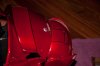
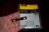
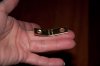
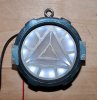
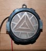
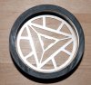
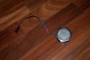
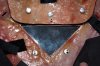
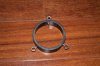
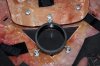
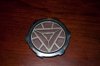
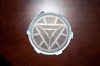
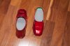
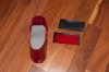
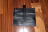
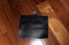
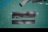
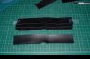
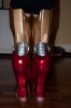
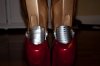
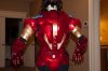
Got my arms connected, but need to get some different Chicago screws...ones without holes in the post sections. I figure I can paint them the same red so they blend in. I also cut some of the flexible cutting mats to put around the inside of the elbow piece and forearms where the other pieces rotate around the Chicago screws. It's thin, but tough, and should prevent scratching and allow the pieces to slide more easily. Also got pieces of thin black foamies glued inside the forearms to prevent the wrist pieces from getting scratched up. Need to do the same for the top part of the cod where the abs and ribs fit down inside and on the inside of the chest, back, and the "ribs" so the abs and ribs don't get scratched up. Also need to attach the hand plates and the rest of the spine sections to the ribs and cod.

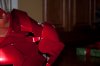
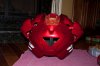
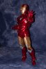
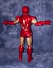
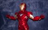
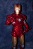
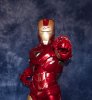
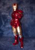
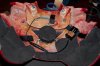
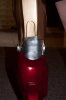
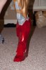
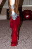
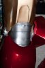
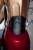
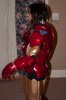
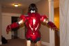
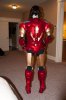
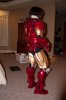
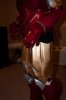
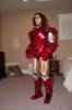
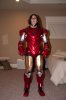
Then I need to figure out where/how to attach the shoulder bells to the back and then attach the arms to the bells. I've been studying other builds to see how others have done it. Got my husband to help me suit up this afternoon so I could see how everything fits. In the pictures, I'm holding some pieces on with tape and I know the abs aren't in the right position. They should be under the ribs, but I was trying to keep everything together without it getting scratched up or falling off.

Did notice I won't really be able to put my arms down without scratching up the sides of the chest and inside of the arms. Guess I'll have to walk around like a steroid fueled weightlifter.:unsure
 

Attachments

  • 20131219-180703--DSC_7944.jpg
    20131219-180703--DSC_7944.jpg
    96.2 KB · Views: 302
  • 20131219-180654--DSC_7943.jpg
    20131219-180654--DSC_7943.jpg
    95.4 KB · Views: 297
  • 20131219-180638--DSC_7941.jpg
    20131219-180638--DSC_7941.jpg
    93.6 KB · Views: 287
  • 20131219-180634--DSC_7940.jpg
    20131219-180634--DSC_7940.jpg
    92.1 KB · Views: 287
  • 20131219-180627--DSC_7939.jpg
    20131219-180627--DSC_7939.jpg
    93.5 KB · Views: 299
  • 20131219-180613--DSC_7937.jpg
    20131219-180613--DSC_7937.jpg
    92.8 KB · Views: 268
  • 20131219-180552--DSC_7935.jpg
    20131219-180552--DSC_7935.jpg
    72.6 KB · Views: 225
  • 20131219-180523--DSC_7932.jpg
    20131219-180523--DSC_7932.jpg
    88.3 KB · Views: 450
  • 20131219-180325--DSC_7927.jpg
    20131219-180325--DSC_7927.jpg
    83.8 KB · Views: 453
I tried webbing and buckles to attach the shoulder bells and arms, and didn't like the way the shoulder bells hung...they sagged, creating a big gap and were too low. I couldn't seem to get the arm assembly to stay up high enough on my arm that way either, so I am trying something different.

I drilled holes for Chicago screws directly into the shoulder of the back (OK how hard is THAT to do to psychologically?!) Bought these mending braces which have predrilled holes that are slightly larger than the post of the Chicago screws. I used 2 part epoxy to set the posts to the bells and used nylon spacers to elevate the bells somewhat so the brace doesn't rub on the edge of the bell. I am going to try leaving the screws connecting the mending brace to the back just tight enough to allow the brace to still swing front to back a bit. Then I'll leave the Chicago screws attached to the shoulder bells even looser, which allows the bell itself to rotate around the screw as well as tilt up and down marginally. So in effect I have a pivot point on the shoulder and a ball and socket joint on the bell. Now to attach the arms. May try webbing attached directly to the Chicago screw holding the brace onto the back. I found using the soldering iron to burn a hole in the nylon webbing makes a great sealed hole that won't tear, so don't even need to use metal eyelets to reinforce the hole.

Maybe will paint the top of the screw red...maybe not. Give the suit a more industrial look perhaps by leaving it silver :unsure
 

Attachments

  • 20131222-233219--DSC_7997.jpg
    20131222-233219--DSC_7997.jpg
    88.3 KB · Views: 177
  • 20131222-233106--DSC_7996.jpg
    20131222-233106--DSC_7996.jpg
    76.7 KB · Views: 161
  • 20131222-233100--DSC_7995.jpg
    20131222-233100--DSC_7995.jpg
    67.8 KB · Views: 183
  • 20131222-233018--DSC_7994.jpg
    20131222-233018--DSC_7994.jpg
    78.1 KB · Views: 223
  • 20131222-192726--DSC_7990.jpg
    20131222-192726--DSC_7990.jpg
    77.6 KB · Views: 162
  • 20131222-192501--DSC_7989.jpg
    20131222-192501--DSC_7989.jpg
    92.5 KB · Views: 156
  • 20131222-192431--DSC_7987.jpg
    20131222-192431--DSC_7987.jpg
    78.8 KB · Views: 173
  • 20131222-192334--DSC_7986.jpg
    20131222-192334--DSC_7986.jpg
    61.2 KB · Views: 151
Worked on getting the arc reactor into the chest. I mounted it from the neck brace using Chicago screws and an eye bolt screwed into the black PVC coupler housing. Then used velcro to keep the wires out of sight. Haven't done anything but get the arc reactor lit up at this point. And it is taped together so I can see how everything is fitting... The shoulders set up like I have them seem to give me fairly good mobility. Not a ton, but enough to move my arms up and down and back and forth somewhat.
 

Attachments

  • DSC_8178.jpg
    DSC_8178.jpg
    83.7 KB · Views: 204
  • DSC_8170.jpg
    DSC_8170.jpg
    92 KB · Views: 205
  • DSC_8169.jpg
    DSC_8169.jpg
    88.7 KB · Views: 166
  • DSC_8166.jpg
    DSC_8166.jpg
    85.5 KB · Views: 165
  • DSC_8164.jpg
    DSC_8164.jpg
    87.5 KB · Views: 194
  • DSC_8163.jpg
    DSC_8163.jpg
    83.8 KB · Views: 196
  • DSC_8160.jpg
    DSC_8160.jpg
    76.6 KB · Views: 152
  • DSC_8157.jpg
    DSC_8157.jpg
    63.9 KB · Views: 140
  • DSC_8125.jpg
    DSC_8125.jpg
    75.2 KB · Views: 181
  • DSC_8196.jpg
    DSC_8196.jpg
    78.9 KB · Views: 112
  • DSC_8195.jpg
    DSC_8195.jpg
    83.3 KB · Views: 106
  • DSC_8194.jpg
    DSC_8194.jpg
    76.8 KB · Views: 111
  • DSC_8190.jpg
    DSC_8190.jpg
    84.1 KB · Views: 114
  • DSC_8113.jpg
    DSC_8113.jpg
    92.8 KB · Views: 234
Got my arc reactor put together and mounted so it's now oriented correctly and won't shift. Used Chicago screws in three places to attach it to the neck brace and chest piece. Just glued the IMC Locknut (silver detail), reactor cover, and sanded acrylic disc on with super glue. Used a circle of black foamie with some aluminum tape on the front, superglued the halo ring to that, then glued the foamie to the back of the back PVC coupler. Used some velcro to keep the wiring under control... Still deciding how to permanently attach the alum triangle cut out and the clear acrylic triangle.:unsure
 

Attachments

  • 20131229-182545--DSC_8217.jpg
    20131229-182545--DSC_8217.jpg
    87.3 KB · Views: 85
  • 20131229-182514--DSC_8215.jpg
    20131229-182514--DSC_8215.jpg
    75.3 KB · Views: 83
  • 20131229-182202--DSC_8213.jpg
    20131229-182202--DSC_8213.jpg
    74.8 KB · Views: 100
  • 20131229-181706--DSC_8211.jpg
    20131229-181706--DSC_8211.jpg
    78.1 KB · Views: 150
  • 20131229-181700--DSC_8210.jpg
    20131229-181700--DSC_8210.jpg
    95.5 KB · Views: 149
  • 20131229-181355--DSC_8209.jpg
    20131229-181355--DSC_8209.jpg
    94.4 KB · Views: 85
  • 20131229-181315--DSC_8208.jpg
    20131229-181315--DSC_8208.jpg
    77.2 KB · Views: 77
  • 20131229-181214--DSC_8207.jpg
    20131229-181214--DSC_8207.jpg
    71.6 KB · Views: 70
  • 20131229-180605--DSC_8205.jpg
    20131229-180605--DSC_8205.jpg
    78.3 KB · Views: 92
  • 20131229-175554--DSC_8203.jpg
    20131229-175554--DSC_8203.jpg
    87 KB · Views: 85
  • 20131229-175534--DSC_8202.jpg
    20131229-175534--DSC_8202.jpg
    80.5 KB · Views: 83
  • 20131229-173656--DSC_8201.jpg
    20131229-173656--DSC_8201.jpg
    86.2 KB · Views: 78
  • 20131229-173644--DSC_8200.jpg
    20131229-173644--DSC_8200.jpg
    96.4 KB · Views: 74
Awesome build! You've given me some inspiration for my next project. Well done!!! Your Table of Contents on Page 1 was very useful.
 
I've been wondering about the Mk VI unibeam for some time. The unibeam on the Mk III & IV is different looking than the actual arc reactor which is hidden behind it in the chest. In the movies, when they are powered all we see is the blinding white light but there are good references for what it looks like when it is off. A few people have done a great job of recreating that piece.

However, I haven't been able to find a good reference photo for what the Mk 6 unibeam looks like when it isn't powered. I'd given thought to doing it for my Mk VI suit just as you have here, using the arc reactor behind either a clear or frosted window. I don't know if someone else out there knows if that's right or what it's supposed to look like. Maybe it's the same round unibeam cover and only the window is a different shape, although that seems like it wouldn't evenly light up the whole triangle. I tend to overthink things. Thoughts?
 
I just seen a few your pics on this thread, and your armor looks amazing! What paints did you use for the suit? The colors you choose make it look very professionally done :D

Sent from my Galaxy Nexus using Tapatalk
 
The only reference pics I've seen where you can actually see the Mark VI unibeam through the triangular window are ones of the actual Hot Toys. I couldn't find any movie pics that really showed the chest where you could see the unibeam through that window and I debated on whether or not I should frost the acrylic triangle or leave it as is and after trying it both ways, I decided to leave it as is. I figured why go through the trouble to make the arc reactor look awesome and then not be able to really see it? I'm not planning on having the arc reactor be removable per say as part of my cosplay, though I can easily take it out for "maintenance." I do have a frosted piece of acrylic that I tried instead and liked the clear one better. I uploaded a pic so you can see the difference.

- - - Updated - - -

one word: AWESOME :D

Thanks ironmaided!
 

Attachments

  • 20131230-085157--DSC_8218.jpg
    20131230-085157--DSC_8218.jpg
    89.9 KB · Views: 93
Duplicolor paints. Inferno Red Metallic, Sunburst Gold, and Silver Frost with 3 coats of Rust-oleum acrylic enamel gloss crystal clear on top

Dang. Can't figure out how to do multi quotes :confused
 
Got my arc reactor put together and mounted so it's now oriented correctly and won't shift. Used Chicago screws in three places to attach it to the neck brace and chest piece. Just glued the IMC Locknut (silver detail), reactor cover, and sanded acrylic disc on with super glue. Used a circle of black foamie with some aluminum tape on the front, superglued the halo ring to that, then glued the foamie to the back of the back PVC coupler. Used some velcro to keep the wiring under control... Still deciding how to permanently attach the alum triangle cut out and the clear acrylic triangle.:unsure
Impressive!. Can you share the LED type, circuit info? I like the arrangement and it looks super bright. I used an led strip for the first one I did but I would like to do a better job for the ones for the kids. I already have theirs 3d printed.
 
Impressive!. Can you share the LED type, circuit info? I like the arrangement and it looks super bright. I used an led strip for the first one I did but I would like to do a better job for the ones for the kids. I already have theirs 3d printed.

Someone else on the RPF used this for their arc reactor too... don't remember who. I tried nesting a smaller one inside the bigger one for a brighter light, but you could really see the hotspots from each of the leds that way, so I went with just the one ring. I liked the way the lights were brighter on the outside and dimmer in the middle. I'm running the ring off a 9v battery, but it is rated to 12V so it could be even brighter.
 

Attachments

  • Screen Shot 2013-12-31 at 1.10.04 AM.png
    Screen Shot 2013-12-31 at 1.10.04 AM.png
    509.1 KB · Views: 132
Still experimenting with gap fillers. The vinyl garage door weather seal works great with the red vinyl paint. I also sprayed a layer of the rust-oleum glossy clear coat on top since the red vinyl paint has a flat finish. The clear coat doesn't crack when the vinyl is bent back and forth, and it makes the red vinyl paint look almost the same as the Duplicator Inferno Red Metallic I used on the rest of the suit.

I used the same weather seal to make the back knee filler. Loctite gel superglue bonds the pieces to each other and to the fiberglass really well! I added another tab to the bottom of the knee piece and punched a hole in it, threaded some thin elastic through the hole and sewed it to itself, then sewed a metal washer on the other end so I could hot glue it down to the back of the shin to keep it in place. (I've found the elastic doesn't remain attached to the fiberglass when it is hot glued, I guess because it stretches and breaks the bond, so adding the washer should work to keep it securely attached. Probably could have sewn a piece of webbing on the end of the elastic instead and accomplished the same thing.) I may remake the vinyl covers I attached to the boot toe. Should have just left a strip bare on the long edge since I can't glue the shorter sides to the inside of the front part of the heel anyway. The vinyl isn't flexible enough to bend if I glued it there, so I'll have to leave the short ends loose.

I don't know if there is a pep out there for the lower boot covers that attach to the shin. I searched and couldn't find one, so created a pattern myself. The vinyl wasn't wide enough to do those, so I used 3mm thick red foam that I sealed and painted instead, but it already has cracks, so I may do something with the vinyl where I layer it in order to make the pieces long enough for that area. I did buy a lawn tractor inner tube to try, thinking it'd be wide enough, but it had seams all on the outside, and when I cut it open, it was kind of textured on the inside.

I've tested other materials for the knee and elbow gaps, like flexible cutting board mats and those plastic shelf liners you put on wire shelves to prevent small stuff from tipping over/falling through, but the paint scratches off. So, I'm still looking for a material that is stiff enough to rivet, takes paint, and is flexible and thin enough to fit inside the elbows and knees since the knees on my suit have so little excess room at the joint. The vinyl is too rubbery to rotate if it's riveted together, so I don't think it would make sense to use it that way since it wouldn't articulate well anyway...unless I put nylon washers in between when I rivet the pieces perhaps...
 

Attachments

  • DSC_8231.jpg
    DSC_8231.jpg
    83.1 KB · Views: 119
  • DSC_8230.jpg
    DSC_8230.jpg
    76.2 KB · Views: 126
  • DSC_8229.jpg
    DSC_8229.jpg
    93.7 KB · Views: 122
  • DSC_8227.jpg
    DSC_8227.jpg
    74.4 KB · Views: 118
  • DSC_8225.jpg
    DSC_8225.jpg
    85.9 KB · Views: 127
  • DSC_8224.jpg
    DSC_8224.jpg
    80.2 KB · Views: 126
  • DSC_8222.jpg
    DSC_8222.jpg
    74.7 KB · Views: 148
  • DSC_8221.jpg
    DSC_8221.jpg
    88.5 KB · Views: 130
  • DSC_8220.jpg
    DSC_8220.jpg
    83.2 KB · Views: 141
  • DSC_8219.jpg
    DSC_8219.jpg
    91.1 KB · Views: 146
  • DSC_8228.jpg
    DSC_8228.jpg
    85.2 KB · Views: 150
  • DSC_8223.jpg
    DSC_8223.jpg
    92.3 KB · Views: 171
Feedback on back of knee gap fillers...The one on the left is the vinyl garage door seal I cut and glued, posting pictures previously. The one on the right is a vinyl runner another member, dfx13, was trying out. I used silver vinyl paint and used a black rub a dub sharpie marker to put on the detail. It needs to be aligned better, but what do you guys think? I didn't detail the one on the left, but it could be done with a sharpie or paint pen too.
 

Attachments

  • DSC_8243.jpg
    DSC_8243.jpg
    97 KB · Views: 156
  • DSC_8242.jpg
    DSC_8242.jpg
    80.2 KB · Views: 205
This thread is more than 8 years old.

Your message may be considered spam for the following reasons:

  1. This thread hasn't been active in some time. A new post in this thread might not contribute constructively to this discussion after so long.
If you wish to reply despite these issues, check the box below before replying.
Be aware that malicious compliance may result in more severe penalties.
Back
Top