TryChick
Well-Known Member
Thanks Zabana, folks like you, Darkside, and Honus sharing their knowledge and pep files are what make our builds possible.Congrats on your work!
Thanks Zabana, folks like you, Darkside, and Honus sharing their knowledge and pep files are what make our builds possible.Congrats on your work!


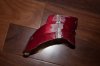
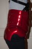
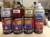
What did you use to paint your suit? I assume spray paint in can form is a bad way to do it so I was thinking of investing in a air brush system.


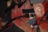
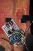
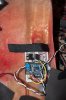
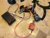
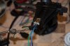
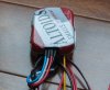
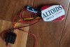
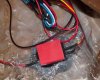
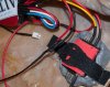
Awesome- looks like you're really close to getting finished! Sent you a PM about your wiring troubles. Are you familiar with Deutsch connectors? Did I tell you about this already?
They make awesome little locking connectors in a bazillion different sizes. They're commonly used in aerospace and motorsport applications. I couldn't believe how cheap some of them were compared to garden variety molex connectors.
http://www.deutschconnector.com/products/deutsch_connectors/deutsch_dt_series_connectors/
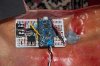
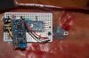
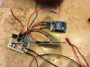
ProwireUSA also sells those connectors. If I had to do it all over again I would definitely have gone that route and probably used Tefzel wire for all of my wiring harnesses since these suits take such a beating.
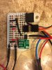
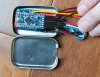
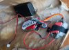
Those Adafruit perma-proto baords rule too. Love 'em!