Let's Talk All Things 3d for prop creation, Scan, Design, Sculpt (real and digital), Print and Finish

Continued to have issues with this set of prints and could not figure out why it was failing. It even clogged the nozzle, which is usually a sign of nozzle impacting the surface.

So, I restarted the print to watch it fail. I have actually discovered something quite unexpected. In Bambu slicer, when switching from normal to tree supports, it no longer correctly adjusts for overlap in reference to the brim.

It continues to warn if you have two objects colliding and a warning for the objects AND the brim leaving the print bed limit. However, it no longer notices the brim of any object colliding with the brim oof another object or that object itself. This allows it to double the thickness at these crossovers which ends in head crash. Set to "normal" supports this did not happen and it would warn of collisions in mapping. But normal supports are difficult to remove and cause damage to the surface they support. I will need to manually separate these print bed items.

20250305_210759.jpg
 
I don’t use Bambu Labs Slicer but most slicing software gives you a 3d preview of the slicing solution. That will show any overlaps in your support structure. Does it not do that?
 
I don’t use Bambu Labs Slicer but most slicing software gives you a 3d preview of the slicing solution. That will show any overlaps in your support structure. Does it not do that?
This does but when it had "normal" turned on it auto merged the supports when overlapping, keeping layer one support at one layer high even though it was sharing that raft/extended angle support for two objects. When I switched to tree it did not lay down one layer shared but rather one layer for each object's supports. But moreso, it warned if there was an issue when set to normal but did not give a warning when set to trees. This then meant that only the visual representation, that you mentioned above, was left to me to make that determination manually. It is definitely there, but I had been conditioned to think it would tell me as the previous raft/brim overlaps were auto adjusted
 
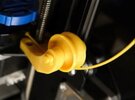
I had my second "non feeding" filament issue and already had my suspicion as to its cause. The filament reel is straight up from the feed motor but the feed motor's intake is horizontal, so 90 degrees to the reel. It already sets off alarms in my head as I expected the reel to feed straight into the motor gears.

I lucked out and was standing there when the incident occurred again. When the gcode (print instructions) tell the printer to load, unload, load, unload the filament, this jittering causes fast intake at the 90 degree intake point and binds. When it binds the load wheel teeth grind away a portion of the filament's edge. When in this jitter mode for too long, it eats away enough of the filament to not be actually touching it any more, no forward or backward movement happens.

Please note: this is NOT the same error as a misaligned feed wheel, worn feed teeth, or weak feed motor.

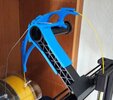
So, I went online and with the correct issue description found several print spool assist adaptations that others have done to overcome this same issue.

20250308_182603.jpg20250308_182549.jpg20250308_182616.jpg

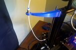
But the print I was wanting to save from failure was already running so I had to improvise. This is a coat hanger and a ribbon roll. Welcome to old school:

20250308_142243.jpg
20250308_142257.jpg


At 41 inches, that ribbon roll was one inch away from being the right answer.
 
Last edited:
greenmachines prompted me to post. So here I go.

I wanted to cover the basics on how I turn a set of pictures, into a full 3d model.
I'm using OnShape, but this process is going to be the same for 360 (or other parametric CAD apps).

I'm going to post a bunch of pics and try to go from "how to hell do I start" to "hey; I've got my first thing".

Step 1:
Scale. Gotta know how big it is right?
In my case I lucked out. One of the pictures I was using as a reference had a measurement on it.
So, you have to get it into your CAD app, and tell it how wide a measurement is. In OnShape, the first time after you've imported a pic, if you put a line on the sketch and then give it a distance, it scales the image to match.

1741501056080.png


So that's step one. Getting some kind of reference thing in place.

I should mention this whole process is going to work OK for things that have "planar" geometry. This gun is mostly good. The handles? Those are a whole other ballgame (of pain). Don't bother trying to do them in CAD. It's hard. Painful.
 
I should have mentioned above: If you pic is not rotated right, square, visible (etc) - then fix all that first BEFORE importing into CAD.
Any "wrong" stuff you import up front stays with you through the entire design process.

Step 2: Find the main thing you want to start with. In my case it was the body.

I made a sketch around the body piece (the yellow bit)
Then I guessed how wide it was and divided by two (I model one half of the gun, and the mirror to the other side to get a full piece).

Guessing involved looking at as many pics as I could, trying to overlay existing distances/sizes from the "60cm" one above, and determining how wide it might be. In the end I think I made it a few mm less-wide, as I thought it looked... right. Of course; if someone else has an actual measurement? Hey, go with that!

1741501332424.png


Taaa daaa.
We've now goto half a gun!

1741501367166.png
 
And so it continues.
Here I've sketched out the trigger block, but I've extruded it slightly less than the body, as it is inset somewhat.

1741501432474.png


You tend to have to come back to some parts later on, as more parts are developed.
I would fine myself revising previous parts and staring at it... thinking: "is that right? does it look thick enough? too thin?"


Rinse. Repeat. A Lot.
I'll stop here. If you've specific questions, happy to do something on those bits.

Other things during this make:
- Lots of subtraction of detail (to get insets, indents and such)
- Use of Blender surface modelling for the handles
- The front grip IS actually done in CAD, using a number of lofts, with guides. Complete. PITA.
- Plugin used for inserting captive nuts. Letting me use proper metric hardware to screw everything together (instead of printed plastic pins).
- 2 x 325mm 16mm dowells through the whole thing to make piecing it together easier.
- STIIICCKERS! (but that's green's realm!!)
 
Another great video on support prep prior to printing to guarantee easy support removal:

Does anyone save their supports?

The more trunk-could be for plants, engine intake manifolds.

One thing I wish I had money and time for—would be to get model bits others think don’t make good spaceship parts-and them me seeing what I could do just with ugly parts.
 
I had my second "non feeding" filament issue and already had my suspicion as to its cause. The filament reel is straight up from the feed motor but the feed motor's intake is horizontal, so 90 degrees to the reel. It already sets of alarms in my head as I expected the reel to feed straight into the motor gears.

I lucked out and was standing there when the incident occurred again. When the gcode (print instructions) tell the printer to load, unload, load, unload the filament, this jittering causes fast intake at the 90 degree intake point and binds. When it binds the load wheel teeth grind away a portion of the filament's edge. When in this jitter mode for too long, it eats away enough of the filament to not be actually touching it any more, no forward or backward movement happens.

Please note: this is NOT the same error as a misaligned feed wheel, worn feed teeth, or weak feed motor.

So, I went online and with the correct issue description found several print spool assist adaptations that others have done to overcome this same issue.

View attachment 1912683View attachment 1912684View attachment 1912685

But the print I was wanting to save from failure was already running so I had to improvise. This is a coat hanger and a ribbon roll. Welcome to old school:

View attachment 1912680View attachment 1912682
View attachment 1912681


At 41 inches, that ribbon roll was one inch away from being the right answer.
Excellent Jerry-rigging that spool greenmachines.
 
I had my second "non feeding" filament issue and already had my suspicion as to its cause. The filament reel is straight up from the feed motor but the feed motor's intake is horizontal, so 90 degrees to the reel. It already sets of alarms in my head as I expected the reel to feed straight into the motor gears.

I lucked out and was standing there when the incident occurred again. When the gcode (print instructions) tell the printer to load, unload, load, unload the filament, this jittering causes fast intake at the 90 degree intake point and binds. When it binds the load wheel teeth grind away a portion of the filament's edge. When in this jitter mode for too long, it eats away enough of the filament to not be actually touching it any more, no forward or backward movement happens.

Please note: this is NOT the same error as a misaligned feed wheel, worn feed teeth, or weak feed motor.

So, I went online and with the correct issue description found several print spool assist adaptations that others have done to overcome this same issue.

View attachment 1912683View attachment 1912684View attachment 1912685

But the print I was wanting to save from failure was already running so I had to improvise. This is a coat hanger and a ribbon roll. Welcome to old school:

View attachment 1912680View attachment 1912682
View attachment 1912681


At 41 inches, that ribbon roll was one inch away from being the right answer.

I picked up a stand-alone spool holder from Amazon.


Works well for me, but I understand that a top mounted takes up less space. Myself, I don't like the top mounted ones because the extra weight of the hardware and the roll, can cause slight torsion in the frame which may affect bed levelling, if there isn't angle brackets to stiffen the frame.

TazMan2000
 
Does anyone save their supports?

The more trunk-could be for plants, engine intake manifolds.

One thing I wish I had money and time for—would be to get model bits others think don’t make good spaceship parts-and them me seeing what I could do just with ugly parts.
So far, I have kept any tree support that had some decent height. They do look very much like tree trunks and exhaust ducting for engines and spaceships. I truly laughed when I read your comment.

So this should give you an idea of how long I have been 3d printing. This is my current tree collection:

20250309_092455.jpg
 
greenmachines prompted me to post. So here I go.

I wanted to cover the basics on how I turn a set of pictures, into a full 3d model.
I'm using OnShape, but this process is going to be the same for 360 (or other parametric CAD apps).

I'm going to post a bunch of pics and try to go from "how to hell do I start" to "hey; I've got my first thing".

Step 1:
Scale. Gotta know how big it is right?
In my case I lucked out. One of the pictures I was using as a reference had a measurement on it.
So, you have to get it into your CAD app, and tell it how wide a measurement is. In OnShape, the first time after you've imported a pic, if you put a line on the sketch and then give it a distance, it scales the image to match.

View attachment 1912736

So that's step one. Getting some kind of reference thing in place.

I should mention this whole process is going to work OK for things that have "planar" geometry. This gun is mostly good. The handles? Those are a whole other ballgame (of pain). Don't bother trying to do them in CAD. It's hard. Painful.
The screenshots make this much easier to grasp thank you.
 
And so it continues.
Here I've sketched out the trigger block, but I've extruded it slightly less than the body, as it is inset somewhat.

View attachment 1912743

You tend to have to come back to some parts later on, as more parts are developed.
I would fine myself revising previous parts and staring at it... thinking: "is that right? does it look thick enough? too thin?"


Rinse. Repeat. A Lot.
I'll stop here. If you've specific questions, happy to do something on those bits.

Other things during this make:
- Lots of subtraction of detail (to get insets, indents and such)
- Use of Blender surface modelling for the handles
- The front grip IS actually done in CAD, using a number of lofts, with guides. Complete. PITA.
- Plugin used for inserting captive nuts. Letting me use proper metric hardware to screw everything together (instead of printed plastic pins).
- 2 x 325mm 16mm dowells through the whole thing to make piecing it together easier.
- STIIICCKERS! (but that's green's realm!!)
I remember seeing one of your screengrabs where the different sections were different colors. Was this to mark whole units? Like one part blocked out in CAD is black and one brought in from another program was blue? I remember thinking it seemed odd at the time because the colors weren't for the finished model skin.
 
I remember seeing one of your screengrabs where the different sections were different colors. Was this to mark whole units? Like one part blocked out in CAD is black and one brought in from another program was blue? I remember thinking it seemed odd at the time because the colors weren't for the finished model skin.
I think most CAD does this for you. It's a simple indication of each separate part, that exists on its own, with no connections to any other part. By connection I mean "welded". Separate parts can still be connected with fixings, but they will still have their own colors.

1741544822917.png


I do notice in OnShape, sometimes a cloned part has the same color tho - see above.

In the above, both the rear "thingies" (orange) and the handle (black) have been translated and copied along the plane of the rear of the body (wow. that's a mouthful). Mirrored. Yeh, that's it.
 
Just a heads up on a possible twist to this thread. I am going to create several collections of links and each will get it's own thread link. I am going to place these thread links in post #1. This will allow any new reader to find these sublists immediately. So far, I have these ideas for sublists:

Steps for scanning, using numerous methods of capture.

Steps for working in mesh toward a solid digital image.

Steps for fully digital, from scratch design.

Slicing/printing software and its use (including scaling, texturing, hardening, hole filling in slicer, etc.).

Printers, printer setup, functions, types, filaments and printer accessories.

Assembly, paint, finish and weathering of printed parts.

Print services or links to same (I don't yet know all the rules on this so am hoping I can get a mod to confirm so we don't do it wrong)

List of free/cheap/paid/subscription scan software.

Scanners, reviews of and links to with alternatives.

List of mesh software free/paid with links.

List of design software .../.. links

List of slicer/print software .../... links

List of utilities (file converters, zippers/unzippers, cutters, splicers, hole fillers, solid makers, mesh converters, etc). The stuff most people forget to mention they used and couldn't have finished without.

File source sites, sales/free/shared.

Please let me know your thoughts on this as I am still new to 3d as well as to rpf. I have been solely focused on cosplay for a while so know very little about other facets of therpf. I will try to keep all updates and convo here and just update the other links with updates to only their list function so no one misses any part of the conversation.

Oh and I will totally be scalping from other convos and posting here with author name if it fits with the idea of knowledge towards successful 3d props. Feel free to do the same.
 
Found another area that needs manual intervention and is, again, unexpected.

When switching from standard supports to trees, I had already determined that it no longer warned if the trees overlapped with other trees. Well, this is even stranger than that. It also does not warn if the trees go outside of the printable area. It did if the standard supports went outside. But it goes a step further because it does see that the tree has left and cuts it planar to the invisible wall that would be the print limit AND fills it in with a new wall at exactly the print limit.

So not only does it not throw a warning but it also renders the preview to look like it is functional even when the top of the tree has been cut off from the bottom.

This means that anything near an edge must be inspected closely before printing.

20250309_144320.jpg
20250309_144334.jpg
 
I had printed Buissonland 's Jod blaster, designed after the first blaster shown with Jod in the Skeleton crew series. The design is so accurate in function that the threaded flash hider threads cleanly and tightly into the blaster barrell threaded front. This is a super clean build with separations in parts that need different paint prep.
20250309_144350.jpg


Notice how both edges of the trees are flat? The same edge limit issue occurred here. I got very lucky in that it did not cause any failures, even on the one that split top from bottom.
 
Does anyone save their supports?

The more trunk-could be for plants, engine intake manifolds.

One thing I wish I had money and time for—would be to get model bits others think don’t make good spaceship parts-and them me seeing what I could do just with ugly parts.
I've a big box of Supports they can be melted with a soldering iron or 3D pen to fill gaps on a large project and even weld pieces together.
There's a YouTube video where the guy dissolved trees into a mushy glue, quite toxic from the look of it but with the correct mask and ventilation.
I'm very new to 3D and having always molded sculpted in the past love this new way of making props I've always wanted to have but not been able too..
It's enabled me to make greeblies for my E-33 ESB blaster and also go down a Tron rabbit hole..
At some point I want to design my own projects but just getting to grips with working in a 3D space and adjusting Stl files and adding trees etc is a learning curve but enjoyable..


I wanted to see how many objects my Bambu could handle in one go..

1000114683.jpg
 
Holes and more holes. Sometimes when a scanned object has holes, the hole repair option will make it worse by making the hole on one face join a hole on another face, creating a passthrough that is very difficult to clean up. So far, my only recourse was to go into edit mode in blender and delete the passthrough by trimming away the chicken wire line by line. Mesh looks very much like chicken wire in edit mode. Once the pass through is completely deleted (including all the annoying inside the body bits it makes) I then select (in edge mode) all of the facets (line segments) around one of the now two existing face holes (one at each face entry) and use the Mesh dropdown to select Merge, at center. this closes the hole and heals the mesh to be saved as a complete body. This is very time consuming and comes into play a lot when doing camera scanned objects. Anyone have tips for hole filling that won't do this? I use hole filling all the time and it usually does excellent but if the faces are back to back on a thin part, this passthrough weirdness happens a lot. Any way of telling it "one face only"?
 
Last edited:
Hard to tell what these machines are “thinking.”

There was a parody of ST:II recently—quite forgettable:
—except for a 3D interpolation you can see at the one minute, thirty-five second mark.

While it is in no way accurate to the refit model itself (the AI only had 2D film image to work with)—-the resulting 3D model is lovely—like a stretched Refit.

That really deserves to live as a physical model.

No other “hallucination” is as lovely.
 
Back
Top