Functional Pip-boy 3000 Mk IV from Fallout 4

Set-up a page somewhere and I'll donate!... I'm sure many others will too!... This work is awesome and guys like you pouring in this kind of effort is awe inspiring. Good job! :)

Just, do us all a favour and put up a parts list and methods for making this ourselves (no pressure!)... I would love to make this!!
 
There is a Paypal donate button on my website: www.zapwizard.com
So far only one person has made a donation in three months. So I am trying not to rely on that, or necessary solicit donations. My bill of materials is a running mess right now. Once I finish my mechanical changes I can get the BOM compete, except for the many little electronic parts.

I am thinking about open sourcing more of the CAD design when it gets closer to being done.
 
Done. :)

I can't access the group-buy survey from here (I'm stuck in the office for a while). Could you add me to your list, please?... I can always do so when home tonight, if not.
 
zapwizard, I understand how RL can kick you in the nuts I hope you have a speedy recovery and your wife as well bro. Take some time for yourself to recuperate from surgery we'll be hete when you return.

Sent from my SAMSUNG-SM-G530AZ using Tapatalk
 
@ Praetor, I saw that announced. It is very cool, and great for many projects. However, the Pi can't run Android, and therefor not be able to run the companion app.

I have two issues with the Pi: One is that they use a processor which no one can purchase for themselves (in small quantities). You are locked to using a Pi module. The 2nd is that they focus almost solely on teaching software with a tiny amount of external hardware. It is great that so many kids get to learn programming on a cheap device, but those same kids also don't get to learn about real, basic electronics. Many learn how to interface one pre-made module to another.
 
I just read all the way through this thread and I'm dying to see where this goes. Maybe if I have the money by the time you finish I'd buy one, since I'm going to be doing a bunch of Fallout cosplay soon.


Hey folks, sorry so long without a major update. I was recovering from my appendectomy, I was on more chems than I like, but now I am able to get back to my office. I also have been playing Fallout way too much, but loving the whole game so far. But I am itching to get back on this project.

So I managed to export the in-game Pip-Boy model. I used the B.A.E. - Bethesda Archive Extractor by jonwd7, and then I exported the to a .OBJ file using NifSkope. I was than able to import this into my CAD software as a reference mesh.

As you can see in the image above I wasn't too far off, not bad considering the lack of reference material at the time. Also, you can see just how much textures, normal maps and tessellation all go into making what is a very low polygon model look so good in-game. The model I exported is the "Hero" model that you see during the loading screens. There is also a lower quality model which has the skeleton arm placed inside.

I scaled the model to 160mm wide to match my design. Note that the Pip-Boy edition is 176mm wide, so mine will be smaller, and I feel more accurate to how it looks on people's arms. One of the Vaults in the game gave me lots of reference in regards to scale.

Here are upcoming list of changes I will be working on in the design:

Mechanical changes:
-Adjust the hinge design (Already visible above)
-Adjust the position of the latch and size of the heatsink detail.
-Tweak the size and position of several parts to better match the in-game model. (Button position tweaks, larger scroll wheel, etc...)
-Re-model the Holotapes to match the game model better.
-Add a velcro strap to secure the Pip-Boy during the time you are attaching it to your arm.

Electrical changes:
-Remove real FM radio. I know many people including me may want this feature, but I am also trying to cut down the cost and complexity to also get the project done quicker. Instead the tuner knob will probably interface to some android application and playback sounds from the game. All the radio music in the game is only 128MB, so it will easily fit onto a SD card.
-Remove the light/sensor pod. Instead this will become a USB cable, able to be detached and plugged into a USB socket for charging or updating. I also plan on making a little table-top module that you can plug into that looks like the Vault door socket.

Other possibilities I am looking at:
-3D Printed master, then cast all the simpler components to help lower the overall BOM costs. (This only done after my first prototype build)
-3D printed master, then cast a soft foam interior. Again, to match the game model. I only recently learned of this process.

A few more donations have rolled in, and I really appreciate it. I will be using those funds to order the LCD touch-screen.
 
Zapwizard,glad to hear that your recovering nicely great job on the corrections to your model.This will definitely be a awesome prop when finished and sadly out of my price range as most props are can't wait to see this prop come to life.
Keep up the great work bro.

Sent from my SAMSUNG-SM-G530AZ using Tapatalk


(FYI: Renderings, not photos)

How is this for a one-day 3D model? I started it just after I made the last post. I imported the 3D model of the in-game holotape. The in-game model is only a few polygons and has no details, but it gives the overall proportions needed. I than overlaid screenshot images to get the little details from the textures. The holotape is thicker and longer than I had in my original model. I think it will fit once I adjust the Pip-Boy model a bit.

After examining the in-game model, I decided that the white thing on the back is a moveable dust cover door. Similar to have a 3.5" floppy would have. But these things are called Holotapes, so I figure they transmit data using a optical technology. So what I did was put a tiny red LED behind the door.

-------------------


But wait, what's inside? Just four super simple electrical components: A coin battery, 56Ohm resistor, toggle switch, and 2mm LED. It can easily be assembled by any beginner.

If I add a cheap Adafruit Trinket 3V Mini board than this can become a real, fully functional Holotape that could transmit a small amount of real data. I may do this to make the design functional on the Pip-Boy. By having the Trinket chip send a single wire serial signal to the LED, and a phototransistor to pick it up, than I can transmit the required unique ID needed to trigger and audio file on the Android side!

If you want to go to the absolute extreme, you could modulate the LED and transmit actual analog audio signals that could be fed to a amplifier. I once had a pair of Sony Wireless headphones which used Infrared. The headphones just had a FM radio receiver inside, but wired to a phototransistor instead of an Antenna. I don't think I will be going to that extreme.

-------------------


Here are all the components exploded.

The screws are real #0 plastic tapping screws, and they are functional. They hold the orange portion of the assembly onto the rest.

But why is the switch hidden inside? Well, at first I wanted the switch to be activated by sliding the door on the back, but the door travels too far for the little switch.
I also looked at tiny lever switches, but I couldn't find any that fit the design well, and no matter what some part would be visible from the outside, breaking the authentic look. Instead what I did was make it so that if you rotate the gray spindle, then it will toggle the switch on and off. The two halves of the spindle snap together making it captive after assembly.

The door snaps onto a rail on the back, allowing it to slide back and forth over the LED. The battery holder is integrated into the 3D model. A few cutouts help route the negative terminal wire.

In the next week or so I will be publishing the full CAD design and BOM for this Holotape design. I plan on making a few of these before I make the Pip-Boy. These can be assembled easily, and only require the parts to be dyed, no major paint work. They will also act as a proof of concept on the tolerances and surface quality I hope to get from SLS printing.

My wife is going in for major surgery tomorrow, and the folks at Udoo haven't released a Android build for the Udoo. So besides CAD tweaks, not much will happen on the actual Pip-Boy for a while.
 
So my wife's surgery went well and she is recovering. I wanted to share a story about a fellow Fallout fan encounter at the Hospital. So there I was waiting for them to call and tell me I could visit my wife in the ICU. When I noticed a Vault Dwellers Survival Guide book across the room. I walked over and found a fellow Fallout 4 fan, also waiting for his wife. I told him what I was building, and about this website. He thought it was all very cool. He loves the game so far, but misunderstood the start of the game and thought that you first played as the mother and then at some point would switch to the father. He was on a xBox so no console commands would help. In either case we chatted for a bit about what we liked about the game. He said I should design some power armor, I told him that there were already people on it, here at the RPF. It was a nice respite in an otherwise already exhausting weekend.

---------------------------
Project update:


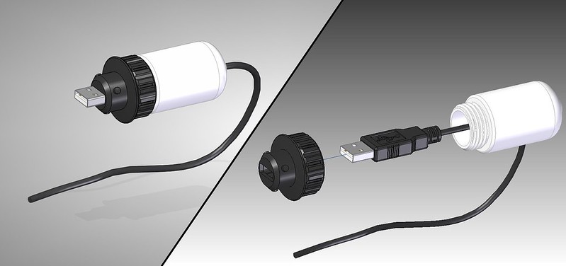
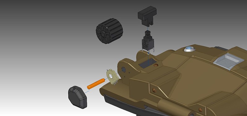
Before I headed to the hospital I designed the custom circuit for the holotape. It will allow the holotapes to actually transmit optical data! Not any real audio or text, but at least transmit a unique ID. The circuit will still use a tiny number of inexpensive components. It could be built by hand, but I plan on doing a small run of PCBs once I get it working on a breadboard.

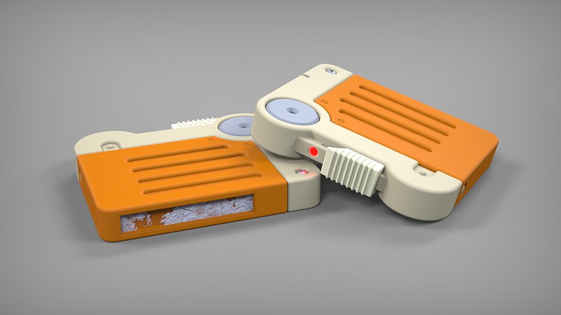
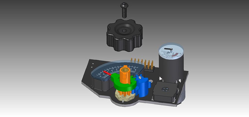
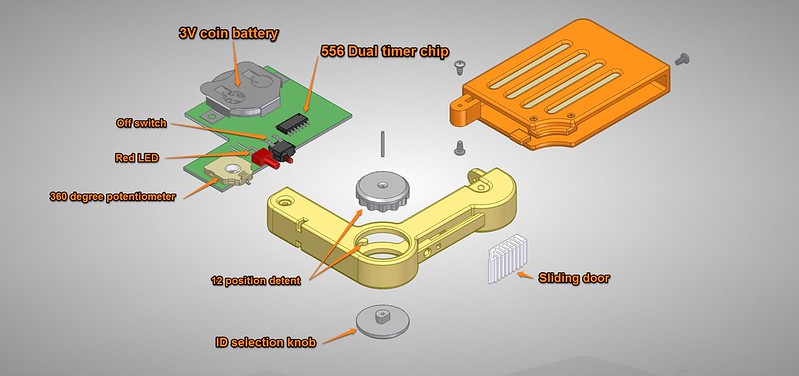
he cool part is that you will be able to change the unique ID of the holotape on the fly simply by rotating the the gray spindle. 12 unique IDs will be made possible with a detent stop on each. However, since the in-game design of the holotape has no markings on the spindle it would be difficult to tell which one you selected. So there will be tick marks into the bottom side of the spindle, the marks could be uniquely colored with a pen, or left alone.


---------------------------


The circuit for the Holotape uses a dual 555 timer chip (556), This chip is one of the workhorses of the electronics industry and if you studied electronics,it is one of the first chips you probably ever made anything with.

Here is how the circuit works, starting at the left:
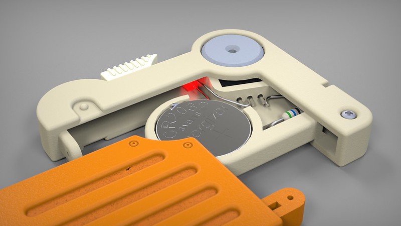
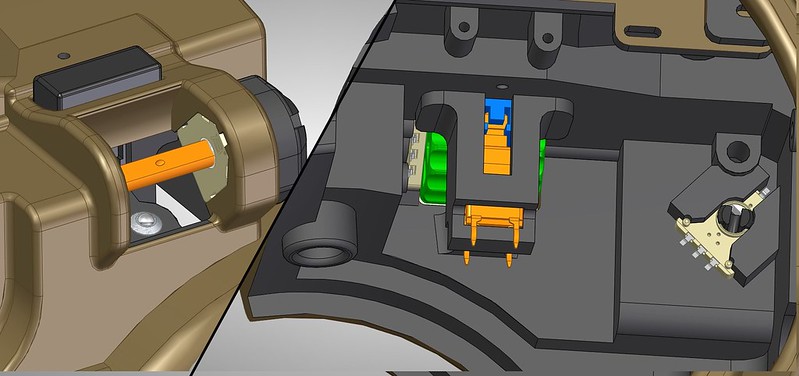
First is a battery for power. Then a cutoff circuit. A PNP transistor blocks all power to the rest of the circuit when the OFF switch is closed. (Why didn't I just use a normally closed sensor switch? They don't make them this tiny.) The switch is a tiny plunger sensor that will be activated anytime the sliding door is closed. So now the holotape only works when the sliding door is opened.

C3 is a bulk capacitor, there to smooth out the battery power, useful since the rest of the circuit is a repeating on/off signal.

The left side of IC1 is a simple 555 timer timer circuit. It creates a repeating digital pulse that is anywhere from 650 to 970ms in length. The potentiometer (RV1) is a variable resistor. By turning the spindle you can alter the timing of the pulse. The spindle will have 12 detents built into the 3D print. This will stop the resistor on 12 possible unique values. Why 12? Well you can only 3D print so small of a detent and have it function properly, and there will be some variation in the actual stopping point of the potentiometer, so by using 12 positions, I gain a 26ms margin of error when detecting the signal. The cool part is you can change the tape ID on the fly.

The right side of the circuit is a 38Khz Modulator. This basically can take in a digital 1 or 0 signal and then puts it onto a 38Khz carrier wave. The carrier wave ensures that the signal can be detected remotely without other signals interfering. This modulated signal is sent out using the red LED. This is actually how your standard IR TV remote works. To receive the signal I use a standard, low cost 38Khz IR remote receiver chip. You will find one of these inside anything controlled with a IR remote. They can be easily connected to a microcontroller.

To detect the unique ID I will be using the "PulseIn" feature built into the Arduino side of the Udoo Neo. This measures the width of any incoming pulse. Read the pulse width, and translate that width into a command and vola! You get a functional holotape that actually uses optical data transmission.

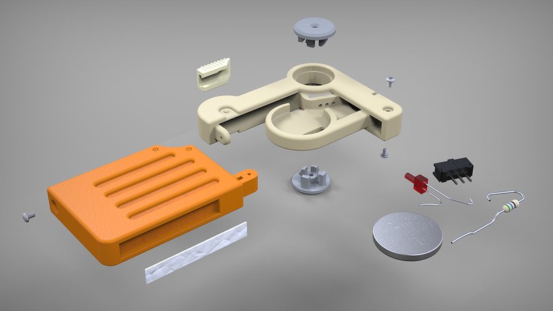
The cost of the circuit should be around $7 + PCB costs (I have yet to make a complete BOM.) The 3D printed portion comes out to $23 on shapeways. The cool part is they can dye the orange part. The white, grey and cream parts would have to be dyed afterwards.

-----------------

Here is a little Fallout error:
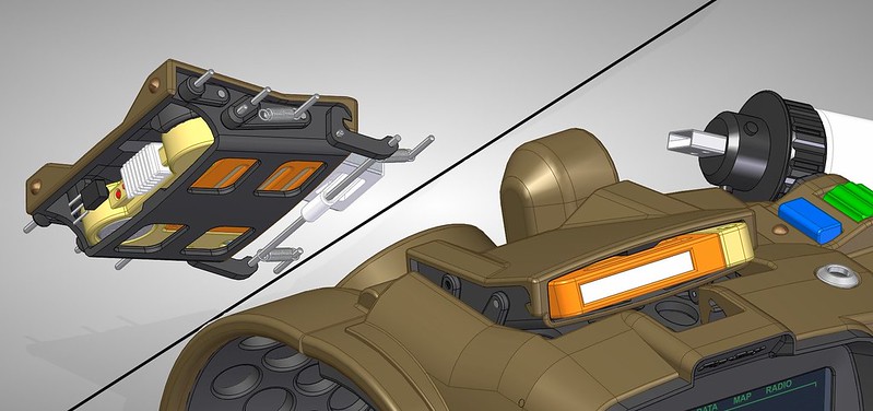
I noticed while designing the holotape that the lone survivor actually puts the holotape into the Pip-Boy up-side down!. At least up side down as compared to the way the tapes show up when placed on a table, or examined in your inventory. (I am using the printed side of the game holotapes as a "top")
 
zapwizard I'm glad your wife's surgery went well I hope she has a speedy recovery.
Great work on the holotapes design your skill is phenomenal cant wait to see this prop finished bro.
Keep up the great work!!

Sent from my SAMSUNG-SM-G530AZ using Tapatalk
 
Last edited by a moderator:
Great... Now my keyboard is all wet from the drool... :D

Glad all is well on the medical front. The latest addition to our brood (just 3 months old) is unwell with a cold and you'd think we've got the plague in the house, so I can't imagine what we'd be going through with surgery to contend with!

This work is excellent, as always. I don't think I've seen such a well-conceived and beautifully designed project. You're making this thing REAL!!


I got a lot of work done on the design this weekend. These are most of the Post-Fallout gameplay changes.

I have done a lot to optimize the overall design. I have lowered the total number of components and this should also lower the end cost.
The first post-Fallout change is the Lamp/Sensor pod will now become a simple USB cable. I am using a ultra-thin cable so that the spring-loaded spool function will still work well.

-------------------------------------------


I found a super useful and tiny potentiometer. I found this while working on the Holotape. It is a 360 degree position sensor, which connects like any typical potentiometer.
it is super-thin, and has a hole through the middle. This has allowed me to use this pot on every knob on the Pip-Boy. Now each knob will simply snap into the Pot. Before I had to have set-screws and multiple 3D printed parts. The extra bonus is now I can connect the tiny knob on the front of the Pip-Boy and gain an extra function.

-------------------------------------------


Because this Pot has a very wide flat profile, I can actually directly mount it into a 3D printed holder. No PCB will be required to mount it. It does means soldering thin wires directly to the Pot, but this again lowers the cost and component count.

Since the Pot can rotate 360 degrees I can use it to replace the rotary encoder. Since it is thin, I can now connect it directly to the selection knob. No gear transfer needed.
I also created a 3D printed holder to hold the selection switch, again eliminating one circuit board.

-------------------------------------------


This smaller pot also allowed me to create more space around the radio knob gear. I re-did the whole design to get a higher gear ratio.

-------------------------------------------


Another major change was the Holotape caddy. I extended the overall length of the holotape caddy. This allows it to fit the new game-accurate holotape design I posted earlier. The data connection to the holotape is now optical instead of a physical electrical connection. This means that perfect direct alignment won't be required. A simple IR receiver chip placed behind the holotape will pick up the signal. The IR receiver chip will be mounted directly on the 3D printed parts, again eliminating another circuit board. Finally I was able to figure out a way to have the holotape partially eject when opened.

-------------------------------------------

There are lots and lots of other small tweaks not really visible. There isn't too much physical changes left to make.
I am still working on the electronics also. I will have to go with a resistive touch-screen, as the China companies I found selling a 3.5" cap-touch panel won't reply to my e-mails. This is typical when they find out you aren't ordering 10,000 qty. Getting the parallel 16-Bit LCD screen connected to the LVDS signalling that the Udoo Neo provides will be a major electrical hurdle to get over.
 

Your message may be considered spam for the following reasons:

If you wish to reply despite these issues, check the box below before replying.
Be aware that malicious compliance may result in more severe penalties.
Back
Top