Phelan Kell
New Member
Hi,
also created an accout to let you know that you are doing a helluva job here. Thank for the docu, files and shared wisdom. My wayto this thread started on YTECs page and when i was reading about improved stuff i had to see it. I started making my pipboy a few weeks ago and.. time is scarce for my hobbies. Anyway the project started as a static prop with maybe space to slide in my mobile. Quickly abandoned that idea after looking through the measurements and .stl files. Then i found (on aliexpress) a 5" LCD Display with HDMI. Ordered it although it fits poorly. Will have to create a bezel to cover up the gaps.
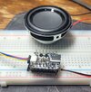
But anyway, with that display i moved away from the plan to creating a little lightshow with an arduino nano. Now i am hesitating to buy one of those raspberry or orange pi Zero 2W to power my pipboy. Prolly it will be the orange, 'cause it has the better technical readings.
Since i really don't know what i am doing with the printed hull right now, i am thinking about it as an MVP and if i can get it properly working i plan of alernating the .stl files according to my changes.
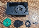
I'll post a few pictures of my Frankensteined stuff later, as soon as my phone is charged ;-)
One Question, bbroerman, in you instructions you refer to the eject mechanism(which you want to overhaul). I can only find .mix files for it. How do i open those?
also created an accout to let you know that you are doing a helluva job here. Thank for the docu, files and shared wisdom. My wayto this thread started on YTECs page and when i was reading about improved stuff i had to see it. I started making my pipboy a few weeks ago and.. time is scarce for my hobbies. Anyway the project started as a static prop with maybe space to slide in my mobile. Quickly abandoned that idea after looking through the measurements and .stl files. Then i found (on aliexpress) a 5" LCD Display with HDMI. Ordered it although it fits poorly. Will have to create a bezel to cover up the gaps.
But anyway, with that display i moved away from the plan to creating a little lightshow with an arduino nano. Now i am hesitating to buy one of those raspberry or orange pi Zero 2W to power my pipboy. Prolly it will be the orange, 'cause it has the better technical readings.
Since i really don't know what i am doing with the printed hull right now, i am thinking about it as an MVP and if i can get it properly working i plan of alernating the .stl files according to my changes.
I'll post a few pictures of my Frankensteined stuff later, as soon as my phone is charged ;-)
One Question, bbroerman, in you instructions you refer to the eject mechanism(which you want to overhaul). I can only find .mix files for it. How do i open those?
 Thanks!