PipBoy 3000 Mk IV from Fallout 4 (mid-grade)

Not sure how I missed this thread, (Just noticed your questions on my thread) you have gotten quite a lot done!
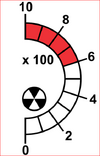
Thanks! I'm trying to get the rad gauge figured out, then I can move on to the tape reel, which is the last main part I have to do. I may add a small RFID reader (also I2C) and put tags in the tapes. Still thinking about that.

This SparkFun controller is driving me nuts :) But I don't have the pins on the arduino to do anything else... unless I can take the I2C that has everything else chained on it, and plug in another Arduino and have it read commands from it. If I can't get this figured out, I may just do that.

When I count by 1 or 2, it goes in a nice circle, once around the block (so to speak) in one call to loop() using the above code in a for loop to count from 0 to 360. If I increment angle by 3 or more, it skips, and each call to loop() only does 1/4 of the circle... I set it up to blink the NeoPixel at the beginning of every loop() call. Since I can't get the Serial debug out to work on this controller, I'm looking at other ways to debug and experiment...
 
I get why you want it all i2C. I was trying to do that earlier on also. I have dozens of i2c boards from Adafruit and Sparkfun. But the Pi Pico has enough GPIO for me to not use it for everything. I stopped using the SparkFun model because it couldn’t hold at any cardinal points (0,90,270).
The reason I determined for this was their controller drops the voltage to one of the two coils when at those angles. When what you need is some current to hold the position, and then more current on the other coil to set the other angle.

The other controller that SimCo puts on their datasheet needs only one pin and may be the way to go.
Possibly, but I'm not sure about generating the proper pulses at the proper frequency to drive it. I can get this one to do enough to ping the rad gauge needle up to 90 degrees, and bounce it around there for a second or so, then bring it back to zero... If I can reliably do that on any of the motors I'm testing with, I'll be good enough. It wouldn't be good enough for your radio, but it may do just enough for the Pip Boy. With the Arduino I started out with, I have no GPIO pins at all I can use. All it had available was I2C.

I am thinking of starting over at some point with a Raspberry Pi Zero 2, then using Adafruits 5" display and the HDMI driver, I can fit that into the model if I cut a little more out, and the benefit is I have all GPIO pins available... But I've already got so much into this, and honestly, this one is just a toy for my son :) Next one may be a showcase version for me. Everything will be the same except for the screen insert it's electronics.
 
Ok, i figured out that the problem is speed... I don't think the gauge motor I have moves fast enough to keep up. It turns very slowly. I've seen that the code I have is correct, when I had it step through 0, 45, 90, 135, and 180 degrees, and held each position for a couple seconds... When I step at +-1 with a 5ms delay in-between each step it can keep up. Any faster and it messes up. SO... we'll see if the next motor I get is faster. That one should be here in a couple weeks. (I'm hoping it's only the motor, and that the controller can keep up)
 
So, now that I have the motor figured out, I am going to have 3 radiation levels (with sounds from the python pyboy code). A very low level, where the gauge is pointing to 1, a medium level where it's pointing to the 4, and then high where it's pointing at 8. Those should be easy to calibrate. I'll set the sounds to last about 10 seconds or so... move the pointer, start the sound, count out 10 seconds, then move it back to zero.

Luckily, the ESP32-S3 has a random number generator that uses wifi or Bluetooth as the entropy source. I can randomly trigger the radiation code.

Unlike the radio sounds, I won't reset the SoundFX card when the radiation sound is playing... it won't play the sounds for the select knob or scroll wheel, but that's what I want when the radiation alarm is running.
 

Attachments

  • Capture.PNG
    Capture.PNG
    43.5 KB · Views: 25
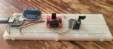
Added the radio dial to my testbed to see how it worked out... Even with the motor controller running (cycling the indicator from 0 - 180 and back), I was able to get somewhat stable readings from the potentiometer. I do think the LEDs are not bright enough though. I'm going to reduce the resistor value by half and see how that looks. I'm way under their current rating.
 
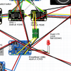
Well, talking to zapwizard, it looks like I grabbed the wrong LEDs... He had 3v LEDs on his BOM and I grabbed 6v LEDs. They *may* still work, though. When hooked up to 5v from the USB directly, they work fine. When running from the ESP32s 4.7 or less power output pin, they don't... So, I ordered 12 of the 3v LEDs to play with, and may keep the current ones (since they'll be driven from the PowerBoost's 5v out) or swap them out. Good thing I have lots of extra PCBs laying around. I also found some nice 6v boost boards, so plenty of options.
 
For a "Plugged in" indicator for the USB (accessory) cord in the back, I'm thinking of adding an opto-isolator from SparkFun (with a 10k pull-down resistor) and hooking the output to one of the GPIO expander pins. That way, when the cord is plugged into a USB port, it can trigger the "Hacking" screen and play the customary sound.

Similarly, for Low Battery, I'll hook up the LBO output from the PowerBoost 1000c to the other opto-isolator input. That will run to another GPIO pin. I'm thinking of adding a sound to that one too, as well as finding a picture of the Pip-Boy (the person) with a thumbs-down and a frown, and showing that with the text "Low Battery" on the display in that condition...
 

Attachments

  • Capture.PNG
    Capture.PNG
    324.9 KB · Views: 27
Ok, so... with 4 radio stations and 2 levels of radiation sounds, I don't have enough triggers on the SoundFX card to do both the low battery, and accessory plug... Now, from what I'm told, when the accessory plug is plugged in, you just get a click and a "Vaut Door Remote Access Ready" screen... so I guess the extra sound trigger will be used for Low Battery. I just have to find an appropriate sound. Also, if anyone is good at graphics, I need a Vault Boy jpeg (or avi) with him frowning and thumbs down. I've been looking all over, and can't find anything yet.
 
Last edited:
Trying to get a clean version of the sound made when you're in power armor without a fusion core. Just that simple beeping. I'm thinking 1 second on, pause for 1 second, then on for a second, and repeat.... Same with the top LED.
 
Got both the large (way too large) air core motor working as well a a super tiny (6mm diameter) stepper. I had to re-write the Arduino stepper library to use the SparkFun I2C motor controller SCMD library instead of just pins... Works really well!

My only concern, really, is what happens if the power is turned off before the stepper is set back to zero? It loses it's position information, so how to re-zero when power is turned back on? Two possibilities I'm thinking about: 1) a spring (or rubber band) that pulls it back to zero when the motor loses power, or 2) a small wiper and metal contact connected to the gear of the motor. rotate it back slowly until the wiper touches the pin (connect wiper to ground, and pin to GPIO input)... thoughts?
 

Attachments

  • 20241113_101959.jpg
    20241113_101959.jpg
    1.6 MB · Views: 21
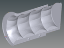
I also started planning the foam liner on the inside of the unit. I made a mold for the padded surface, that fits over the front / back of the main body. I'm looking at using either Foam Putty, or FlexFoam-iT!™ 6. I'll probably try the Foam Putty first as I have local friends familiar with it. Either way, I can make the foam padding, then some spray adhesive to put cloth over it, and maybe some light stitching in the creases to help hold it all together better. (I like a mechanical connection in addition to just glue)
 

Attachments

  • Capture.PNG
    Capture.PNG
    332.2 KB · Views: 15
Found a 5v stepper (20 steps per rotation, or about 18 degrees per step) that's under 10mm in diameter, with a 7mm output shaft that should work if I glue it to the bottom of the PCB directly... I also found a 8,, x 7mm x 2mm micro limit switch (spst normally open) that I can try to fit in there to let it "auto zero" on startup, so that if power goes off while the motor is not at zero, it can find zero again when it's turned back on. Just connect it to a GPIO or the ADC... Still looking for a smaller one if I can find one...
 
Greetings! Made an account only to ask you one thing. Is Phone version (100%) currently supported at least in some way?
I would like to use Ytec's model with an actual phone (Iphone 12 mini), but I also like your project and having some extra moving details would be great. Considering that I won't be ordering any circuit boards, adafruit overall is not available for me, and I would rather just focus on adding a couple of purely mechanical details and some simple LEDs here and there.
If it's possible, please tell me what I can print and use for that build.
well, I'm working on scaling the different things down to fit on the 100% version, but have a long way to go on it... but I wouldn't have the foggiest idea of how to interface things like the select knob, scroll wheel, etc. to the phone. I also didn't like the idea of having a huge gap on the top and the bottom of the phone, which is why I printed a "caddy" in the first place, to take up the space between the phone and the model... I guess the question is what extra details are you looking for, and how much interaction do you want with things? I mean, you can always clip off the scroll wheel from Ytec's model in meshmixer and add a smaller version of my knob. With the select button, you could make it smaller, and glue on a spring or 2 to give it some movement. The other knobs are screwed on, so it's just a matter of not tightening them all down so much. The only real difference is the tape deck. I haven't gotten that far yet, but from everything else I've done on scaling it down, it should work ok. Just load up Ytec's parts in meshmixer, then load up my tape deck parts, then scale them down to match his. After that, it's a matter of a) can you print them that small and get the printer to do it cleanly (FDM has much larger minimum feature sizes), and can you find the hardware (screws, rods, pins, springs, etc) that fit at that size. Like I said, I haven't gotten that far on the 100% version yet, but probably will once this one is completely done.
 
I looked over what I have on the 100%, and it's just the electronics caddy, the mold for the screen cover, the select knob, scroll wheel, and select button, and the first part of the tape deck (not the push-to-eject part, just the part that locks the lid, and pops it up), and the power switch. I haven't scaled down the radio dial, the push-to-eject part of the tape deck, or the USB cord reel yet. I have a workable mechanism for the Rad gauge, but like the other one, it is only for the SimCo MAC. I haven't tried looking at that yet with the stepper and limit switch.
 
Here's a link to the tape deck part scaled for the 100% model (what I have so far): PB3k Mk4 100% Tape Deck.mix

I haven't tried printing this yet, so I can't guarantee anything. It still uses the 2mm rods I found on Amazon, so that's good... Not sure at all about printing the small round catch on the bottom of the tape door at that scale with an FDM printer. You may need to SLA print the tape deck door, or replace those pins with some other hardware pins screwed in or glued on... not sure yet.
 
I just looked at the radio dial assembly, for both the 115% and the 100%, and the 100% version is much smaller... so I'm going to have to mess with that one a good bit to get everything to fit (i.e. the gears) and line up properly. The PCB for the LEDs is also going to be way too big, so that will need to be redesigned too.
 
well, I'm working on scaling the different things down to fit on the 100% version, but have a long way to go on it... but I wouldn't have the foggiest idea of how to interface things like the select knob, scroll wheel, etc. to the phone. I also didn't like the idea of having a huge gap on the top and the bottom of the phone, which is why I printed a "caddy" in the first place, to take up the space between the phone and the model... I guess the question is what extra details are you looking for, and how much interaction do you want with things? I mean, you can always clip off the scroll wheel from Ytec's model in meshmixer and add a smaller version of my knob. With the select button, you could make it smaller, and glue on a spring or 2 to give it some movement. The other knobs are screwed on, so it's just a matter of not tightening them all down so much. The only real difference is the tape deck. I haven't gotten that far yet, but from everything else I've done on scaling it down, it should work ok. Just load up Ytec's parts in meshmixer, then load up my tape deck parts, then scale them down to match his. After that, it's a matter of a) can you print them that small and get the printer to do it cleanly (FDM has much larger minimum feature sizes), and can you find the hardware (screws, rods, pins, springs, etc) that fit at that size. Like I said, I haven't gotten that far on the 100% version yet, but probably will once this one is completely done.
Not much functionality is needed. A holotape mechanism would be nice to have, also that USB screw-in thing from zap's design.
Functionality-wise I only want some LEDs, working radio dial, and hopefully a small powerbank somewhere in there.
Generally I just want that pipboy to feel "mechanic", so you can rotate a knob and it'll feel like a knob that does something.
 
"So, I'm working on building a PipBoy 3000, Mk IV for my oldest son."

So, the number of men and women on this site whom I am going to have to get to adopt me is astounding, and just keeps growing!

LOL! That perk has a prerequisite: Must be my nephew. ;)
Haven't worked that one out yet...
 
Back
Top