If you’re drilling tubes you should really be using stepped drill bits. They won’t catch and tear out the sides of the tube wall, plus you can make a counter-sink with the chamfer of a larger size.

You are using an out of date browser. It may not display this or other websites correctly.
You should upgrade or use an alternative browser.
You should upgrade or use an alternative browser.
Double Pipes!!! (Stunt lightsabers)
- Thread starter thd9791
- Start date
newmagrathea
Sr Member
Don’t buy these, buy bigger... you reach your limits real quick with them
But,... but money. I'll have to bug you when I get serious about buying on what to look for.
I'm excited to see these developments on the blade. I'm not really into the lights and sounds, but the motorized spinning blades is right up my alley.
But,... but money. I'll have to bug you when I get serious about buying on what to look for.
I'm excited to see these developments on the blade. I'm not really into the lights and sounds, but the motorized spinning blades is right up my alley.
Make sure you contact me before you buy anything
Don’t buy these, buy bigger... you reach your limits real quick with them
Can vouch for this. I have a mini-lathe and benchtop mill, as well. The mill is good for small things and hasn't given me grief at all, but the lathe... If you get one, know you'll sink at least 1.5x your investment just to get it "decent." Belts are super hard to find and short of you just modding the whole gear and belt set-up, you're stuck using the exact crap belts to replace your crap belt. It's the reason I have 2 to spare on hand for mine.

Can vouch for this. I have a mini-lathe and benchtop mill, as well. The mill is good for small things and hasn't given me grief at all, but the lathe... If you get one, know you'll sink at least 1.5x your investment just to get it "decent." Belts are super hard to find and short of you just modding the whole gear and belt set-up, you're stuck using the exact crap belts to replace your crap belt. It's the reason I have 2 to spare on hand for mine.
100% agree, what bench lathe do you use?
You use a mill my size for the pommelcubes ?
Mine's one of those awful blue, cast iron monstrosities multiple vendors slap multiple names on. So, you know...quality.
Whatever the 7x14 version of this to be exact:

So far I've had to remount and build a custom rig for the motor, had to add a lock nut to the cradle, replaced the tool mount and post, replaced two of the awful plastic gear with two slightly-less-awful steel gears (because the replacement set I have does not entirely fit the way my lathe was built), also making a new catch for the main gear to actually lock the gear to the drive shaft; completely re-arranged the wiring so I could make modifications and repairs easier, replaced the fuse system with a better trip fuse set up, and still I have to replace the tailstock center dial as the crap plastic it's made from broke in half and figure a way to keep the shield from catching on the chuck beyond keeping it propped up with a nail. I've not attempted to try threading on this as it means I have to undo practically all my modifications to re-orient the gears.
I imagine you've had to go through similar, Halliwax ?
Whatever the 7x14 version of this to be exact:
So far I've had to remount and build a custom rig for the motor, had to add a lock nut to the cradle, replaced the tool mount and post, replaced two of the awful plastic gear with two slightly-less-awful steel gears (because the replacement set I have does not entirely fit the way my lathe was built), also making a new catch for the main gear to actually lock the gear to the drive shaft; completely re-arranged the wiring so I could make modifications and repairs easier, replaced the fuse system with a better trip fuse set up, and still I have to replace the tailstock center dial as the crap plastic it's made from broke in half and figure a way to keep the shield from catching on the chuck beyond keeping it propped up with a nail. I've not attempted to try threading on this as it means I have to undo practically all my modifications to re-orient the gears.
I imagine you've had to go through similar, Halliwax ?
Mine's one of those awful blue, cast iron monstrosities multiple vendors slap multiple names on. So, you know...quality.
Whatever the 7x14 version of this to be exact:
View attachment 1339149
So far I've had to remount and build a custom rig for the motor, had to add a lock nut to the cradle, replaced the tool mount and post, replaced two of the awful plastic gear with two slightly-less-awful steel gears (because the replacement set I have does not entirely fit the way my lathe was built), also making a new catch for the main gear to actually lock the gear to the drive shaft; completely re-arranged the wiring so I could make modifications and repairs easier, replaced the fuse system with a better trip fuse set up, and still I have to replace the tailstock center dial as the crap plastic it's made from broke in half and figure a way to keep the shield from catching on the chuck beyond keeping it propped up with a nail.
I imagine you've had to go through similar, Halliwax ?
Exactly, got almost 2k into mine.. stripped those damn gears so many times... had enough.. broke that lathe 3 times..
Still to this day have never had a successful “parting” on it.. can’t part a thing to save my life, followed all the YouTube videos.. can’t do it.
End up cutting it where I need it parted with a band saw then putting it in the lathe the other way and cleaning it that way..
Need a bigger machine
Still to this day have never had a successful “parting” on it.. can’t part a thing to save my life, followed all the YouTube videos.. can’t do it.
End up cutting it where I need it parted with a band saw then putting it in the lathe the other way and cleaning it that way..
I'd do the same if I had a band saw. I can part on my lathe but I get super-nervous when I do. It screams like a 1000 cats in heat. My trick is have the parting tool just slightly under center and keep it well oiled while cutting while brushing any chips away. It always drifts from where I want it cut but I can finesse it enough where I can account for it. Once it's cut deep enough, it won't kick or get budged off my cut line. I also reduce the speed when I'm close to cutting through and part is slowly; like I'm shaving with the tool bits.
I'd love a big, old, German-built lathe had I the space and car to move it into. They are literally built like tanks.
You use a mill my size for the pommelcubes ?
Yeah, it's not actually very difficult to do; just slow. I'm sure I'd get cleaner outcomes had I rotating-dial-clamp-thing but pommels are pretty easy to figure out to do. Again, just slow.
Last edited:
Yeah, it's not actually very difficult to do; just slow. I'm sure I'd get cleaner outcomes had I rotating-dial-clamp-thing but pommels are pretty easy to figure out to do. Again, just slow.
Could you use a hexagonal collet block for the pommel cubes or would you need a full indexing rotary table?
You could; I don't for no other reason than I just have limited space and resources. I just mark what I need to cut on my pommels, mill the channels, then turn and mill the angles in my bench vice. That's the most bare bones things you really need... Beyond precision and patience.
Also, I think this is how they cut the pommels for the movie. Since every cube is a little off, they must have done each recess slowlyYou could; I don't for no other reason than I just have limited space and resources. I just mark what I need to cut on my pommels, mill the channels, then turn and mill the angles in my bench vice. That's the most bare bones things you really need... Beyond precision and patience.
I think all of the props were done by eye; there's just too many blemishes, asymmetrical details on everything for them not to have been. I want to capture that in what I'm doing, too. Maybe without even you realizing it, Tom, but you're doing things just as authentically as the real things most likely would've been.
Every knick, ever ding, every covered-up screw-up; it would be just as the original makers would've gone through and done, as well.
Every knick, ever ding, every covered-up screw-up; it would be just as the original makers would've gone through and done, as well.
I have good and bad news.
the scoop style of countersinking bits worked beautifully. I got really slick holes!!! I used the saber hilt I ruined by chatter/blowing out the holes as an experiment and cleaned up the holes.
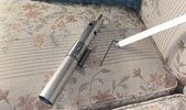
what’s the angle of these standard black countersunk bolts? I think these are the right angle - because the core still slides a little. It’s small but the bolts aren’t gripping the outer tube again..
im hoping it’s only because the holes are too wide? Everything else looks right, I already drilled these holes too big last time so I’m not surprised if that’s the case
1st and 2nd “saved” hilt


also what are peoples opinions on a flat area vs a lathed ring for blade set screws on the tang?
the scoop style of countersinking bits worked beautifully. I got really slick holes!!! I used the saber hilt I ruined by chatter/blowing out the holes as an experiment and cleaned up the holes.
what’s the angle of these standard black countersunk bolts? I think these are the right angle - because the core still slides a little. It’s small but the bolts aren’t gripping the outer tube again..
im hoping it’s only because the holes are too wide? Everything else looks right, I already drilled these holes too big last time so I’m not surprised if that’s the case
1st and 2nd “saved” hilt
also what are peoples opinions on a flat area vs a lathed ring for blade set screws on the tang?
LOM
Well-Known Member
Lookin' great!
These seem real tough to get exact. It looks like the hole is a tad too large and/or deep on the 'saved' one to my eyes but I'm probably not the best person to answer that. Although not a mechanical connection, maybe putting glue under the bolt heads would help keep it tighter to the outer tube?
For the blade tang, I'd bet on a lathed ring a la the Vader RotJ stunt:
...also what are peoples opinions on a flat area vs a lathed ring for blade set screws on the tang?
...For the blade tang, I'd bet on a lathed ring a la the Vader RotJ stunt:
View attachment 1373588
Lathed cut, most like. Also credited to be on the V2 by Brandon Alinger, too.
SO, previously, I struggled with the bolts on these. I couldn't get them flush, or at least unnoticeably low. I stopped after I bored out the first one too much and the second is still undone.
I decided to go back to the drawing board and do another from scratch!

I did this more methodically than anything previously. I want to thank Sym-Cha for measuring the bolts on the real props for me. I judged the 12mm heads to be M6 Black Oxide bolts. I found some vintage ones online. I saved the ones with no logo for a DV6 in the future, these at least have very fine writing on them.
I found the center of the core using a center finder ruler thing and roofing nails to scratch the metal. The sharpie wasn't accurate enough

I stepped up drill bits and bored out the core for whatever leftover steel I had lying around, 3/8 round


then drilled and tapped an M5 set screw into the core.
I got excited and put it together only to have to disassemble it to carve the emitter! I used a half round basturd file and rolled the shape... hard to describe but I've done it 4 times now
Then.....
unfortunately, I had to:
1) disassemble the saber
2) assemble only the tube and core - drill and tap M6 holes
3) disassemble it again to put the tang in, screw in the grub screw
4) reassemble and countersink the M6 holes


This was such a pain, I really am starting to think they used a die and cut threads into the end of the tang. (That is something I don't know how to do properly) Why was it a pain? EVERYTHING WAS PRESSURE FIT THIS TIME. I used a 15" long Construction hammer, and scrap tubing and wooden dowels to hammer these things together. I used sand paper and metal files to trim a few thousands off... its hard to describe but you can tell when things are close and can be pressure fit together... but man, I had to hammer these parts together and hammer them a part over and over. it would be so much easier with threading.. would that be more sturdy too? I bet threaded studs exist?!
Anyway, I used zero-flute countersinking bits (and matched the degree/angle of the bolts) and lots of Rapid Tap cutting fluid and look at the holes!


Right now I only have one 3/8 antenna blade. It was on my original pipe stunt, and the other one is a blue taped ski pole. Gotta make myself another 3/8 bored antenna. So, I popped my ol' CX-4 on the tang (which I stripped in a drill press) and..


I decided to go back to the drawing board and do another from scratch!
I did this more methodically than anything previously. I want to thank Sym-Cha for measuring the bolts on the real props for me. I judged the 12mm heads to be M6 Black Oxide bolts. I found some vintage ones online. I saved the ones with no logo for a DV6 in the future, these at least have very fine writing on them.
I found the center of the core using a center finder ruler thing and roofing nails to scratch the metal. The sharpie wasn't accurate enough
I stepped up drill bits and bored out the core for whatever leftover steel I had lying around, 3/8 round
then drilled and tapped an M5 set screw into the core.
I got excited and put it together only to have to disassemble it to carve the emitter! I used a half round basturd file and rolled the shape... hard to describe but I've done it 4 times now
Then.....
unfortunately, I had to:
1) disassemble the saber
2) assemble only the tube and core - drill and tap M6 holes
3) disassemble it again to put the tang in, screw in the grub screw
4) reassemble and countersink the M6 holes
This was such a pain, I really am starting to think they used a die and cut threads into the end of the tang. (That is something I don't know how to do properly) Why was it a pain? EVERYTHING WAS PRESSURE FIT THIS TIME. I used a 15" long Construction hammer, and scrap tubing and wooden dowels to hammer these things together. I used sand paper and metal files to trim a few thousands off... its hard to describe but you can tell when things are close and can be pressure fit together... but man, I had to hammer these parts together and hammer them a part over and over. it would be so much easier with threading.. would that be more sturdy too? I bet threaded studs exist?!
Anyway, I used zero-flute countersinking bits (and matched the degree/angle of the bolts) and lots of Rapid Tap cutting fluid and look at the holes!
Right now I only have one 3/8 antenna blade. It was on my original pipe stunt, and the other one is a blue taped ski pole. Gotta make myself another 3/8 bored antenna. So, I popped my ol' CX-4 on the tang (which I stripped in a drill press) and..
Attachments
I successfully put a blade together for this one. Tapered inner spacer and collar from aluminum, M5 set screws
I specifically went and bought some carriage bolts and wing nuts designated to my drill press trimming because I was always scrambling for a bolt to trim these!


I think I’ve memorized this process by now
I specifically went and bought some carriage bolts and wing nuts designated to my drill press trimming because I was always scrambling for a bolt to trim these!
I think I’ve memorized this process by now
Attachments
ID10T
Sr Member
Countersinking needs to be done s l o w l y.
Fewer flutes can help in aluminum, brass and leaded copper (wood too) but you still have to go slow. Sometimes wax or soap can help as a lubricant. But usually dry, just very low rpm. Faster just chatters more, and they get quite deep quite fast that way.
And if you want a countersink to pull parts together, you have to machine them that way. Drill the tap hole through both pieces and then tap it. (Use a bottom tap after the starter tap if it’s a blind hole). Countersink the assembly so the head sits where you want it. (Open the outer part with the through hole drill if it’s not thin) THEN disassemble it and countersink the inner part a bit deeper. If there is no gap, there is no means for clamping. If you know your clearance (say 0.010) then add three thousandths to that (0.013 in this example) and countersink the inner part an additional 0.013
Now, for holes: I don’t care if you do drill them on the lathe with a perfectly centered tailstock- the drill will always follow the existing hole. So if the original hole is off center, angled, or whatever, the new hole will be too. Just at the larger diameter. The only way to straighten a hole is to bore it.* I just went though this last week with a bunch of tooling with off center tapped holes. I also added a counterbore for a shoulder bolt and I drilled about 0.010 under final diameter and bored the last bit to final straight and true diameter.
*sometimes you can cheat using a solid carbide drill or an endmil to drill the hole. But it only works for shallow holes with stiff tools that side cut. Boring is the right way.
Wow, thanks so much! ID10T can you go into more detail about clamping in countersinks? I've had success countersinking the parts at once and have been getting a shiny smooth hole with both parts flush with these new zero bits
Also, some updates! I cleaned out the foam in this blade that over filled into the tang hole. I then used the existing little threaded hole to make a stand-in red button, I'm guessing that was its purpose during filming, wanted to see what it looked like. From the reports it seemed like just a threaded hole in the tube that led into the shroud area, not a blind hole straight into metal (the core). This is as low as I can go to be above the core anyway, it's a representation of the prop and I really like the look.


Oh yea.. the button? Look what I made!

I believe this was a Larbel... an ooolllddd red button replica that just had paper towels stuffed into the housing. I machined an adapter to match the inner flanges of the button. After such a success... I thought I should be a true machinist and hold the adapter in the button mechanically, which means another set screw!


Also, some updates! I cleaned out the foam in this blade that over filled into the tang hole. I then used the existing little threaded hole to make a stand-in red button, I'm guessing that was its purpose during filming, wanted to see what it looked like. From the reports it seemed like just a threaded hole in the tube that led into the shroud area, not a blind hole straight into metal (the core). This is as low as I can go to be above the core anyway, it's a representation of the prop and I really like the look.
Oh yea.. the button? Look what I made!
I believe this was a Larbel... an ooolllddd red button replica that just had paper towels stuffed into the housing. I machined an adapter to match the inner flanges of the button. After such a success... I thought I should be a true machinist and hold the adapter in the button mechanically, which means another set screw!
ID10T
Sr Member
It's looking good!
Just to create a clamping force with a countersink, you first do the normal countersink, to get the head flush (or how you want it to be), and then disassemble. On the inner (in this case) part, you then use the countersink to deepen the partial countersink on that part slightly. Depending on assembly tolerances, I like to have 0.003" clear. So if the parts fit together tightly, probably 0.005 would be good. If it's a slip-fit (which has .003 or more clearance already) you might go to 0.010 under on the inner piece. Or good old trial and error method.
What you want to do, is allow the threads to pull the piece up, rather than having the countersink bottomed out, which may not pull the inner piece up tight against the outer part. You need clearance for the countersink, and making it a bit deeper on the inner piece allows this.
Similar threads
- Replies
- 1
- Views
- 1,317
- Replies
- 24
- Views
- 3,203
- Replies
- 39
- Views
- 12,077
Done / Completed
**LINEAGE** Foundry Cast ANH Kenobi Stunt Hilts (ANH/ROTJ - V2/V3)
- Replies
- 367
- Views
- 61,142