The New Core - Tom's Accurized ESB Stunt

thd9791

Master Member
RPF PREMIUM MEMBER
Okay - so I built my first ESB Graflex stunt before I really knew a good chunk of what we do now. It used a Ski Pole as a blade, had random bolt placement, the core was too heavy and it used a threaded rod. Thankfully, the inaccurate modern CX-4 blade I made (coated in 3M Graphic film) technically fit because I drilled that to 3/8, so I got to pair it with a white reflective blade.

I don't have it anymore. It was sold to a family friend in the northeast US who saw Star Wars multiple times a day when it came out in theaters. He is absolutely head over heels and it makes me really happy!

Anyways, that leaves an empty space in my collection. Tom the Bolt Hunter is at it again.

Two things are bothering me.
1) We still don't know how the tang was held in. The countersunk bolts I'm 90% sure just hold the core assembly to the flash. I have embedded a grub screw in the Pipe Stunt core because we only see the 4 outer bolts. Tang removal is impossible with the core slid into the saber. (Granted, I hammered it into the saber)

EDIT: wait, maybe the little threaded hole in the pipe stunt also goes to the tang!? I always thought that was for the red button. The tapped hole does go into the core, but very high up, so I didn't think it was for structural use. Maybe not...

2) All the bolts are usually covered by Mark Hamill or Bob Anderson's hands... or aluminum foil. I'm not mad at him, of course not. The weight of the stunt saber is right behind the bolts. To properly fence you need your hands there. For us PropReplica makers, that makes this very tough.

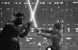
scottjua shot I think
empire08-vi.jpg
empire04b-vi.jpg
Screen Shot 2019-07-09 at 1.09.39 PM.png


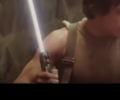
Is this next one a scottjua picture
Luke-skywalker-vs-darth-vader-duel-behinds-scenes.jpg
Bespinduel5.jpg
PRIVATELukeWindow.jpeg
Screen Shot 2020-12-18 at 11.13.38 AM.png
Screen Shot 2019-03-01 at 9.35.45 AM.png


Following is the start of my research. I finally color-coded for my use.

Now, I'll start with this weird thing. The upper "puck" as I call it. The upper 1/3 of the socket is replaced by metal. Maybe they broke the upper piece.... because in some shots I don't see the evidence in the socket. There is also a mark on the side in some shots, that could be a bolt. I can't tell. If not.. we are missing a bolt for this part. The front 4-40 screw is not enough. I've tried this and the back flops up
Screen Shot 2019-11-30 at 6.39.00 PM.png
Screen Shot 2019-11-30 at 6.39.19 PM.png

UpperSocketBolt.jpg

uppersocketproof1.jpg


I think it's painted black here, and the side-profile is hidden by the Vader Shroud. Thank you Parts of SW lonepigeon
127002062_3285005278288730_4925843145502776737_n.jpeg


Now, onto the bolts. I always thought they added more for the woodchop scene... maybe? I can't find the little group of 3 on the back (for example) in any ESB shots. I also cannot find any with bolts in the clamp. (The V3 mystery clamp) I started to think these might be the same saber when I noticed this off-set bolt
DVMOMleft.jpeg
Screen Shot 2020-04-03 at 2.29.37 PM.png


C'mon what are the chances of putting it there twice! There really isn't a reason to offset the bolt.
And now for some others....

The Right Side Bolt
DV61.jpg

RBoltToss.jpg
FrontRightBolt.jpg


The Left Side Bolt
DV62.jpg


???????

The Front Offset Bolt
DV63.jpg

FrontBolt.jpg


The Back Bolt
DV64.jpg


backboltChamber.jpg


backboltHamilatready.jpg


BackBolt1.jpg


So....yea... no left side bolt yet, no group of 3 on the back and no confirmed puck screws. And no tang access.
Unless they heavily lathed down bar stock to a snug fit, 1-3/8 round bar fits inside a graflex with a hair of wiggle room. My pipe stunt needed a press-fit to be snug, so maybe I'll use packing tape, but that may be too thick!


I have a real 3 cell with a nasty clamp and a thin knurled button ready for this project. I've hit a bit of a wall research wise..
 

Attachments

  • BespinFight.jpg
    BespinFight.jpg
    102.2 KB · Views: 62
  • Screen Shot 2021-10-03 at 6.58.48 PM.png
    Screen Shot 2021-10-03 at 6.58.48 PM.png
    750.9 KB · Views: 72
Nice research!! Following ! I didn’t really understand this stunt. I mean I do but with so many other variants of the graflexs during the entirety of the shooting of the film... not sure why they chose this one for the stunt sequences during this part...interesting for sure!
 
Nice research!! Following ! I didn’t really understand this stunt. I mean I do but with so many other variants of the graflexs during the entirety of the shooting of the film... not sure why they chose this one for the stunt sequences during this part...interesting for sure!
Thank you! Other people's excitement is good motivation to follow this through. Quite bluntly... I'm pretty sure they rigged 1 or 2 Graflexes up for stunt work so the bladed thing was convincing when it was in frame. Everything done to it was for a practical reason, from drilled bolts all the way down to the foam grips.

It was more convincing than the pipe stunts too, though for all intents and purposes they both look the same when watching the movie
 
Oh yes I agree! I’m just curious is all.. they had a different graflex for different shots ( dagobah , Hoth, cloud city etc.. all with different anomalies ) I’m sure they had several stunts but to why they chose one with heiland features made to look like a graflex when they had so many others lol. But yes..
One of the reasons why I love the RPF so much is the amount of research and deep diving into the props used.. really it’s an incredible catalogue and plethora of information.. all because of people like you. Bravo!
 
Also have you checked the graflex bank? There is some interesting information there about that saber as well. Not sure if it’s the same one though .
ESB Gallery
 
Tom, dont we have anderson on record saying he wanted more weight added to the lower section of the ROTJ vader stunt? i swear there is a story going around where he wanted more weight to balance the blade... maybe thats the reason for the back bolts, they ended up making a new internal setup, and added more mounting bolts?

idk..

but i do think you are on to something here with the colored circles, i can follow it much easier that way
 
LOL rereading I may have misunderstood. I think you are talking about something all together different .. disregard my last post! :p:lol:
 
Given the new research in this thread
The LV ( Luke and Vader ) Shared Stunt Lightsaber

You should know I’m updating this project. I do have a real 3 cell spare here, and I nabbed my Folmer button from the first version I made.

After gutting it, I took the middle part of the socket, one of the wannawanga aluminum discs and enough aluminum to go down to the slot on the upper half. 1-3/8 diameter

So, I couldn’t have done this without Roy’s part, it already had a center hole. So I put it in a vice with my aluminum and made 5/16 holes in both. I took a long time, new bits and lots of rapid tap cutting oil…. And bored 2/3 of the way into the main core.
1BD44B19-E1D2-44E2-9347-E9B8A2A2AD20.jpeg

Then, you’ll love this, I used the graflex socket to drill and tap two 6-32 screws to hold the socket to the core… because Roy’s part already had recessed for screw heads! His plastic core needs those screws so I thought why not copy it for my metal one! I stacked them in the 3 cell bottom to drill pilot holes using the socket as a jig
0AAE201A-0386-4ADC-9FF1-232056170ECF.jpeg

I ran an M4 grub screw through the side and stuck a 5/16 threaded rod in there. I used Roy’s part as a jig to drill a hole in the socket piece too.. and stacked them all on a rod with a wing nut on top.

I took a dremel to the threaded rod, threw the whole thing in a drill press and sanded it for a few minutes (my vintage graflex didn’t quite fit Roy’s part, so I had to reduce the diameter) and now all 3 sections are the same flush diameter

I did it as a press fit, so with some taps, the whole thing slides into place. Seen here posing with one of my antenna blades.. I took the blade from my barbican blades ESB stunt for a moment. I’ll have to make another one for this… still needs a 5/16 mild steel tang … and lots of bolts

125454C9-D61F-45D5-90EA-C32DA0898C09.jpeg
 
It’s going to take me a while but I’m slowly putting the bolts in. So, for others who want to build this, I have a system now.

Roy did an amazing job, that template is almost exactly spot on. I’m not totally sure about the smaller upper bolts, they may be more asymmetrical, but anyways look at the two bolts along the back. One is under the ball catch on the DV6 and the other is the center of the 3. Sorry this photo is of the other side haha
FD288803-64EE-4749-87D7-0173DF89E4A8.jpeg

I taped his template to my flash body and noticed those two were lined up along the flash.. but a few degrees off of the red button. It’s so little that I double checked the reference and that’s correct. It’s like less than 2mm and it’s freaking right.

Anyway, here is my system.

1) grab an engraving bit that’s a cone or a really small ball cutting bit and put it in your rotary tool. Like a pencil, press that bit into the center mark of your hole
0F37F43D-6798-47BA-AAFD-75B0D499BC0B.jpeg

2) grab a cheap set of center finding bits. They’re chunky, with a reduced tip. asavage did a whole video on it, twist bits tend to bend or skip and spin and can ruin your hole placement. Even in a small area. The chunky ones are less likely to bend and they seem to have a sharper and more accurate tip.

Use one that doesn’t get bigger than your main bit.

This is for the main body bolts. When it comes to the top piece, I’m going to do the M3 bolts and the 4-40 graflex screw. The body ones are M6

3) bore down with a 5mm bit. Hopefully at this point you’ve already made your center hole for the tang. That means this hole will blow out into the empty center. You can stick a rat tail file in there later, for now this is good.
6A5A66B5-997B-4EBD-8ACA-16F67837F5FE.jpeg

4) Start an M6 tap with a hand drill that has a safety. Forward, backward, inch it down little by little. Once it’s really in there, change to a longer hand tap handle, you get more lateral force and the tactile feedback of what’s happening inside. A drill helps your starting threads come out clean and straight. Smaller taps I stay with the drill.

4) take a zero-flute countersinking bit and open the hole for the bolt head. Stop and check frequently so you can hand cut it to the exact size you need. On this saber some bolts are flush front to back and other bolts have oval holes so they’re flush side to side. Boring into a tube means you’ll never have the whole circumference flush.. if you go too far you won’t have much of the outer shell to grip!
9DA90BB9-0865-4297-B781-3E23A24FDF3A.jpeg
419C40F5-DD60-4F2C-96D4-3DC423475B72.jpeg

Boom, tighten your black bolts down. I use rapid tap cutting oil to drill as well as tap.

Currently on ice. I leaned on a drill press vice too close to the edge of the table and it went straight down on my toes. Thankfully in leather shoes but still..


2C216518-34E8-442E-9DE3-AD1063494071.jpeg
 
Here’s where I’m stopping tonight. 4 of 7 body bolts done… then the 2 in the upper core.. and the little graflex screw

I also found a good board for this clamp. No fat trace… but really accurate leads
C00D328D-526A-4C1A-BA82-B16ED9C4D12C.jpeg
 
I finished the body bolts, and did the 4-40 for the top disc. All I have left are the M3 bolts on both sides of the red button. I have some new thoughts.

Again, I wondered why the hell they would put so many bolts in this. It crossed my mind, maybe they put two pieces of aluminum in the back, leading to the two rows of bolts. Still, don’t know why they’d need 3 in a row and then 1 on the other side.

My flash was actually out of round. There’s a decent gap around 1/3 of the core if you look at it inside. The bolts helped add pressure and even out the pressure around the core. Maybe they had similar problems and tried to re-shape the flash to make it a circle again?

Anyway, my cores shifted when drilling, about 1/16 upwards. Thankfully there was still enough material for the 4-40 tap, there are just spiral impressions underneath the disc haha. I broke the tap so if I re-do this I’ll have to grab another. I did have to countersunk the aluminum for the slotted screw as well, as a side note.

My bolts are all pretty flush, much cleaner than my first one and they are all different types of flush, like the original prop. Also like the original prop, this got scratched to hell when I was machining it. No wonder they tried to polish the upper!
45F5C680-1DD4-4972-AE4B-C23BCC410F15.jpeg
80CA3104-4165-4875-A0EF-B1C3E9E29724.jpeg
83636930-0CCD-403B-AEFB-97FBBAC45BA8.jpeg
14D68546-B9F7-4883-B33F-300AF79438A3.jpeg
EDEFD861-7C64-409E-B9B4-2813FD259075.jpeg
2903C98E-4F6A-4623-A7F1-B15858B27075.jpeg
87AF5F67-C4C4-40D1-8D74-A39AE99C39E3.jpeg
5C879F0D-A28D-425F-A97E-A2E3FBCDBF7C.jpeg
2D648019-71E6-42BB-884F-26C6FF84AB90.jpeg
67947181-A3E3-4871-BF0A-BBC3DE2F02F1.jpeg
4025C890-A268-4B58-9A09-1FBB4206EC9E.jpeg
 
Oh yea, my “3 in a row” bolt holes actually meet near the center of the core. Chips from one hole came out of the others! I needed them deep enough to run normal M6 taps through and they do meet. So I’m using a shorter bolt in the center one, just to keep things away from eachother.
 
I never knew of this saber before a few month ago but it's super cool! I'm such a fan of the VD6 so I loving this one as well! the early red button on it makes it even cooler in my books :) cool stuff Tom :)
 

Your message may be considered spam for the following reasons:

If you wish to reply despite these issues, check the box below before replying.
Be aware that malicious compliance may result in more severe penalties.
Back
Top