You are using an out of date browser. It may not display this or other websites correctly.
You should upgrade or use an alternative browser.
You should upgrade or use an alternative browser.
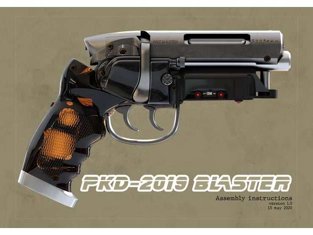
Blade Runner PKD blaster / That Gun
- Thread starter BeardySi
- Start date
-
- Tags
- blade runner blaster fallout
BeardySi
Active Member
Quick question for the other blaster fans out there - has anyone got an stl file for the binding post part and for the muzzle end of the top? Both are areas of this kit that I'd like to improve on - would be a handy shortcut if I could print them rather than fiddle about with a lathe...
Hopefully some more updates later - I'm typing this while waiting for filler to harden
Hopefully some more updates later - I'm typing this while waiting for filler to harden
Noeland
Master Member
You might find what you need here:
 www.thingiverse.com
PKD-2019 Blade Runner blaster. by AndersFP
I have printed at 0.2 layer height for the most part. The small parts (triggers and switches) ar printed at 0.05 layer height to get all the detail.Version history:1.01:Unfortunately I discovered a problem with the clip - I made the "on/off box" too big, so the switch lever did not protrude far...
www.thingiverse.com
BeardySi
Active Member
You might find what you need here:
Looks like that'll have what I need, thanks!
So, an update!
I wasn't happy with the Steyr bolt area - the fit was poor and the shape wasn't quite right. I reshaped the bolt to a better profile, removing a fair bit of material in the process.
Thankfully I finally got some body filler so I can now get properly stuck in. I built up the missing areas and filled the gaps between the parts for a really good fit, then sanded them back together to get a really smooth profile.
I also attacked the Steyr receiver part, reshaping both sides to better reflect the original. I packed out some of the meeting faces with styrene to tighten up the fit. It's still not 100% and the upper reciver needs some gap filling where it joins as there's a big gap.
At this stage I'm just removing the cast screw heads as a matter of course. I've got replacements for them all on order so I'm guessing waiting for those to arrive will be the next big delay
Last edited:
BeardySi
Active Member
Nice work! Making lemonade from lemons.
Are you using Bondo for the filler?
Steve
Isopon - car body filler. Bondo is the same kinda stuff I think (don't get it here).
Last edited:
Excellent work polishing those grips, do you have any tips you could pass along, mine are a bit foggy as well.Thanks for the tips Mark. I did realise after a while that those pics weren't of the original but I'll live! I'm using an album of the prop from Worldcon for detail references so I've got it covered. That said, all I'm really trying to do is correct some of the more glaring (to me) inaccuracies of the PKD-2 design and come up with a happy medium between the two - don't plan on going too mad with it!
Got the grips polished. Some pitting came up on one which was annoying - will deal with it later. The polish really showed up the unmixed pigment which I'm really unhappy with. Against a white background it stands out quite a bit.
View attachment 1291418
View attachment 1291423
They do look better against a brushed steel finish, so hopefully they'll be OK. If not I'll mould them and vacuum cast a better set - don't particularly want to go to that bother, but we'll see how it looks at the end...
View attachment 1291421View attachment 1291422
BeardySi
Active Member
Excellent work polishing those grips, do you have any tips you could pass along, mine are a bit foggy as well.
Thanks. I used polishing wheels on a bench grinder to get at really deep polish. It's fast, you only need to work it to 800 grit by hand and it gives the best finish by far.
The trick to getting a really good polish is to work up the grades of paper and make sure you eliminate the marks from the coarser grades before you move on to the next.
Use a reasonably coarse paper to smooth out the casting - 240 or 180 or so. Try and do all of your sanding in one direction. When you move on to a finer grade sand at right angles to the direction of the previous grade and you can see when you've taken out all of the coarser scratches. Work up the grades 320, 400, 600, 800. I'll normally start wet sanding around 600.
Always try and sand in one direction rather than in a circular motion - you'll never see when you've removed all the coarser scratches if they're swirls and any you do miss will stick out like a sore thumb on the final polish.
If I'm using a wheel, I'll stop at 800 and use medium and fine compounds on soft wheels.
If I can't use a wheel I'd go for a polishing mop in a dremel with a polish like T-Cut or Auto Glym. In that case I'd continue hand sanding to 2000 grit before polishing.
You can get a decent result without a dremel too - use the back of a piece of fine wet and dry (the paper side) to work the surface with T-Cut or your polish of choice.
Fantastic advice, thank you so much for taking the time to respond. Excited to get my grips looking like yours.Thanks. I used polishing wheels on a bench grinder to get at really deep polish. It's fast, you only need to work it to 800 grit by hand and it gives the best finish by far.
The trick to getting a really good polish is to work up the grades of paper and make sure you eliminate the marks from the coarser grades before you move on to the next.
Use a reasonably coarse paper to smooth out the casting - 240 or 180 or so. Try and do all of your sanding in one direction. When you move on to a finer grade sand at right angles to the direction of the previous grade and you can see when you've taken out all of the coarser scratches. Work up the grades 320, 400, 600, 800. I'll normally start wet sanding around 600.
Always try and sand in one direction rather than in a circular motion - you'll never see when you've removed all the coarser scratches if they're swirls and any you do miss will stick out like a sore thumb on the final polish.
If I'm using a wheel, I'll stop at 800 and use medium and fine compounds on soft wheels.
If I can't use a wheel I'd go for a polishing mop in a dremel with a polish like T-Cut or Auto Glym. In that case I'd continue hand sanding to 2000 grit before polishing.
You can get a decent result without a dremel too - use the back of a piece of fine wet and dry (the paper side) to work the surface with T-Cut or your polish of choice.
BeardySi
Active Member
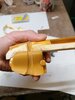
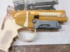
Some parts fresh off the SLA machine!

A correct front end and binding post, along with a Steyr safety and screwdriver thingy to replace the kit ones which were so bad it wasn't worth fixing them. Those two parts seem a bit bigger than they should be (at least for this kit) so I'll sort that out.
I printed a weaver knob, but I'm in two minds whether I'll use it or go with the slotted screw.
I also printed a Steyr logo to go on the bottom of the mag. Probably should have made it a bit more curved but I didn't have the kit part to hand when I did the cad. Such is life...
BeardySi
Active Member
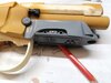
Here's a case of modelmaker OCD in action...
The insert with the ejector port detail on the kit isn't representative of the real thing, plus it's a terrible fit. Couldn't be having that!

I originally made up a new insert moulded to the slot on the receiver, but I still wasn't happy with it. Ultimately it looked like a piece that was dropped onto a hole rather than a bolt behind the port.
There was only one thing for it, time to get carving! I opened up the ejector port to the inside of the part and widened the back of the hole to give the appearance of the real thing. At the same time I cut out the awful looking front end to make way for my printed replacement.

I used a piece of cardboard tube of the right diameter to make a filler mould, covering it with scotch tape to keep the filler from sticking. When it was set, I taped up the inner face of the mould and filled it with filler to make my bolt.
Some sanding and fitting later and I've got a bolt that fits neatly into the ejector port - I still need to add the detail to it.
It was rather a lot of work for what appears to be very little difference, but it looks a hell of a lot better to me!


The new front end was a fairly simple matter of cutting a recess and dropping in the printed replacement. Some filling of the gaps and sanding to the right profile and it was done and dusted. It looks one hell of lot better!

Overall a very dusty weekend of cutting, carving, filling and sanding, but it's really improved two problem areas of the kit.
The insert with the ejector port detail on the kit isn't representative of the real thing, plus it's a terrible fit. Couldn't be having that!
I originally made up a new insert moulded to the slot on the receiver, but I still wasn't happy with it. Ultimately it looked like a piece that was dropped onto a hole rather than a bolt behind the port.
There was only one thing for it, time to get carving! I opened up the ejector port to the inside of the part and widened the back of the hole to give the appearance of the real thing. At the same time I cut out the awful looking front end to make way for my printed replacement.
I used a piece of cardboard tube of the right diameter to make a filler mould, covering it with scotch tape to keep the filler from sticking. When it was set, I taped up the inner face of the mould and filled it with filler to make my bolt.
Some sanding and fitting later and I've got a bolt that fits neatly into the ejector port - I still need to add the detail to it.
It was rather a lot of work for what appears to be very little difference, but it looks a hell of a lot better to me!
The new front end was a fairly simple matter of cutting a recess and dropping in the printed replacement. Some filling of the gaps and sanding to the right profile and it was done and dusted. It looks one hell of lot better!
Overall a very dusty weekend of cutting, carving, filling and sanding, but it's really improved two problem areas of the kit.
BeardySi
Active Member
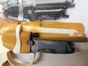
Oh god, I've done it again! I swear I just can't help myself!
Despite blending it down with filler, I still wasn't very happy with the fit of the upper Steyr receiver - particularly at the back end of it. It just didn't look right to me with the upper reciver sitting stop the lower and not behind it.

The only thing for it was to carve a channel in the lower receiver part, extend the sides of the upper and then back fill the lower to meet it. That would make it much more presentable and have the join going in the right direction to my eye...


There's still some reshaping of the curves at the back needed, but it's already looking much better to me. I didn't do anything on the other side as that seam will eventually be hidden.
A lot of work for something so seemingly inconsequential, but I'm the one who'll have to look at it!

Despite blending it down with filler, I still wasn't very happy with the fit of the upper Steyr receiver - particularly at the back end of it. It just didn't look right to me with the upper reciver sitting stop the lower and not behind it.
The only thing for it was to carve a channel in the lower receiver part, extend the sides of the upper and then back fill the lower to meet it. That would make it much more presentable and have the join going in the right direction to my eye...
There's still some reshaping of the curves at the back needed, but it's already looking much better to me. I didn't do anything on the other side as that seam will eventually be hidden.
A lot of work for something so seemingly inconsequential, but I'm the one who'll have to look at it!
Attachments
BeardySi
Active Member
Progress! I've pretty much finished fettling and adjusting the shape of the major components and am starting to prep surfaces for paint. Everything now is a tight fit and locates well.
Replaced the Steyr logo on the foot of the mag, realised too late that I'd printed an inset logo rather than a raised one. As it's all going to be a satin black it'll not be too visible anyway, I can live with that!
The mag foot now sits neatly into the magwell. I also added the missing switch - a dummy in this case as I had to cut one down to size. I'll control the lights from elsewhere later on...


Decided to replace the big slotted screw with the weaver knob, so did that and located the binding post at the same time. I also added the groove onto the new plate for the ejector port.


Overall its beginning to take shape nicely, though shipping delays are melting my head.
Next big jobs are replace the trigger guard and fit the triggers (waiting for material), add all the screws (waiting for screws) and sort the wiring - at least I've got everything I need for that!
Replaced the Steyr logo on the foot of the mag, realised too late that I'd printed an inset logo rather than a raised one. As it's all going to be a satin black it'll not be too visible anyway, I can live with that!
The mag foot now sits neatly into the magwell. I also added the missing switch - a dummy in this case as I had to cut one down to size. I'll control the lights from elsewhere later on...
Decided to replace the big slotted screw with the weaver knob, so did that and located the binding post at the same time. I also added the groove onto the new plate for the ejector port.
Overall its beginning to take shape nicely, though shipping delays are melting my head.
Next big jobs are replace the trigger guard and fit the triggers (waiting for material), add all the screws (waiting for screws) and sort the wiring - at least I've got everything I need for that!
Attachments
joberg
Legendary Member
You're doing one hell of a job transforming that prop.") Saying that and knowing the history of that recast of a recast of a recast (I could go on and on) and the fact that Rick Ross (RPF member) did the first one, looking at bad pics from a VHS tape of the movie and getting the results that you've held in your hand is, in itself, quite good. What makes this gun interesting in the history of the different makers who, along the years, made their own interpretations of the weapon (until it surfaced at World Con and was photographed by Karl...another RPF member) is that each has their beautiful "faults" that make them special. The slotted screw, for example, is screen accurate; not the one that was replaced on the World Con gun (ironic that one). As far as I'm concerned, I would've built (and fix) the prop and would have left it as is...but that's me.
Saying that and knowing the history of that recast of a recast of a recast (I could go on and on) and the fact that Rick Ross (RPF member) did the first one, looking at bad pics from a VHS tape of the movie and getting the results that you've held in your hand is, in itself, quite good. What makes this gun interesting in the history of the different makers who, along the years, made their own interpretations of the weapon (until it surfaced at World Con and was photographed by Karl...another RPF member) is that each has their beautiful "faults" that make them special. The slotted screw, for example, is screen accurate; not the one that was replaced on the World Con gun (ironic that one). As far as I'm concerned, I would've built (and fix) the prop and would have left it as is...but that's me.
Keep up the great work!!
Saying that and knowing the history of that recast of a recast of a recast (I could go on and on) and the fact that Rick Ross (RPF member) did the first one, looking at bad pics from a VHS tape of the movie and getting the results that you've held in your hand is, in itself, quite good. What makes this gun interesting in the history of the different makers who, along the years, made their own interpretations of the weapon (until it surfaced at World Con and was photographed by Karl...another RPF member) is that each has their beautiful "faults" that make them special. The slotted screw, for example, is screen accurate; not the one that was replaced on the World Con gun (ironic that one). As far as I'm concerned, I would've built (and fix) the prop and would have left it as is...but that's me.Keep up the great work!!
BeardySi
Active Member
You're doing one hell of a job transforming that prop.
Keep up the great work!!
Thanks, I'm rather enjoying this build. My wife was quite annoyed that this kit was a bit of a mare, but I'd much rather a build I can really get stuck into rather than something that can be glued together and painted in a day...
Before I started I did quite a bit of digging into the origins of the kit - I'm constantly amazed at how good a job Rick Ross did with his interpretation given the lack of any good source material at the time. I think if I had an original kit (chance would be a fine thing!) I'd build it as designed, but as it's a shonky recast I've given myself some latitude to improve a few areas.
I was torn with the issue of the weaver knob. I know it didn't feature on the prop at the beginning and there's a question over whether it was ever on the prop during filming. To me, it looks better, so for now I'll keep it - it can always be changed out at a letter date very easily if I change my mind. Something that couldn't have been done if I'd left the cast one in place
BeardySi
Active Member
Small update tonight.
Royal Mail seems to have got moving again and a flurry of packages (some 6 weeks late!) arrived this week, including all my screws. I've spent far too much time fiddling with tiny screws, modifying tiny screws, drilling holes and generally being driven mad by screws Still, things are looking good, even if most of the screwheads won't go on until all the priming is done - no point in risking losing the detail!


I've removed most of the text from the Steyr receiver as it was beyond saving with pin bubbles. Thankfully the Pflager-Katsumata text is OK - I want to keep that. I'm thinking of SLA printing the serial number and Steyr-mannlicher text and insetting them into the appropriate places.
Started work on a new trigger guard. Will also fabricate two new triggers from aluminium.

I've also been considering wiring. The kit had the 5 red LED's wired in parallel to 2 AAA batteries. I'm thinking of having the triggers switch on and off the lighting - one for the reds and one for the greens. I've ordered two of the smallest push-on/push-off switches I could find so I'll see waht I can do there....
Royal Mail seems to have got moving again and a flurry of packages (some 6 weeks late!) arrived this week, including all my screws. I've spent far too much time fiddling with tiny screws, modifying tiny screws, drilling holes and generally being driven mad by screws Still, things are looking good, even if most of the screwheads won't go on until all the priming is done - no point in risking losing the detail!
I've removed most of the text from the Steyr receiver as it was beyond saving with pin bubbles. Thankfully the Pflager-Katsumata text is OK - I want to keep that. I'm thinking of SLA printing the serial number and Steyr-mannlicher text and insetting them into the appropriate places.
Started work on a new trigger guard. Will also fabricate two new triggers from aluminium.
I've also been considering wiring. The kit had the 5 red LED's wired in parallel to 2 AAA batteries. I'm thinking of having the triggers switch on and off the lighting - one for the reds and one for the greens. I've ordered two of the smallest push-on/push-off switches I could find so I'll see waht I can do there....
Similar threads
- Replies
- 3
- Views
- 185
- Replies
- 3
- Views
- 673