An ILM R2 Story

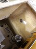
The part that made the motor install so great was this right-angle drive.

DeWalt Rt Angle.JPG


The yellow part is just a shaft support and handle. Once it comes off, you are left with a very compact unit.
The removable phillips bit sits in a standard hex-drive hole. I machined the drill's output shaft to fit that hex, and mounted the angle drive
to the face of the drill motor with an aluminum plate.


18.2 Shaft mod 4.jpg


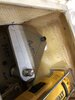
I cut off the threaded part, which is where the drill chuck would screw on, and then machined the stub to have the hex profile to fit into the angle drive.

18.2 Shaft mod 3.jpg


18.2 Shaft mod 6.jpg
 
18.3 Gearbox 2 copy.jpg


Here is the new motor mounted to the old gear cluster.
You can see how the angle drive's mounting plate is held on to the face of the motor's gearbox by the long all-thread pieces with lock nuts on the ends. It even allows me to switch the gearbox's high and low gear still.
It may look a little janky, but it's very secure.

I ended up eventually ditching the old gear cluster. The motor has a built in gearbox, so the additional gearing just made the robot move agonizingly slow, while the motors were screaming at high rpms.
I'll post the test video as soon as I figure out how to convert an .mov file to a mp4. This site doesn't seem to allow .mov files.
 
Last edited:
I guess I'd thought that it would have given better low speed control, but I hadn't considered the noise it would create.

So the extra gearing had to go!

In this pic you can see the gear cluster. I've already removed the chain that connected it to the wheel sprocket. I pulled out both gears and instead put a sprocket on the motor shaft, and then a chain directly to the wheel. This took out almost a 30 to 1 gear reduction. The DeWalts are plenty strong enough to drive him around right at the shaft. I don't what I was thinking.

18.3 Foot 7 copy.jpg


The chain on the lower side of the wheel is to transfer power to the second wheel. So he's actually 4-wheel drive! Mud bogging - here we come!

The other benefit of having 4 wheels, is that R2 is stable in 2-leg mode 'cuz he has 4 points of contact.
I have to be careful, but I can drive him around on 2 legs too.
 
Last edited:
The other place I used a DeWalt motor was for the 3rd leg extension. I used a recycled ILM motion control model-mover as the slider for this. We used these onstage for shoots, and they are very stable, compact and strong. It didn't have a motor on it, so I set up a motor mount and drive belt to spin the lead screw to extend his middle leg.

18.4 Mid Extend 5 copy.jpg


And here it is with the middle leg/foot installed:

18.4 Mid Extend 2 copy.jpg


Now you may be asking "Hey Dude! What's with all the plywood?" "Why not use aluminum?"

Well, I coulda' .... but aluminum is expensive. And heavy compared to plywood. R2 gets freaking heavy by the time you get everything in to him.
So anywhere you can reduce weight is a good idea. Also wood is easier to cut, drill & glue - and is surprising strong when used properly.
 
Now that the drive motors were sorted out; and before I could work on cosmetics, it was time to turn to the task of getting all of R2's arms/legs and feet to swing about in a controlled manner.
Uncontrolled = not good :p

This brings up a subject of semantics that has stymied me for many years: Does R2 have "Arms" or "Legs"?
- Everyone seems to agree that the trapezoidal boxes that touch the floor are "feet", and that the round-topped appendages on either side of his dome are "shoulders".

....shoulders go on arms, but feet go on legs.....? :unsure:

So at what point do his arms become legs? Does he have legs with shoulders? Arms with feet? Should the shoulders instead be called hips? Even though they are up by his head? Does the word "should" actually mean a single "shoulder", or part of one?
These gut-wrenching existential questions may never be adequately answered.....

....but I digress.....


Eschewing the conjoined shoulder-pivot-to-ankle-pivot linkage, I instead chose to use individual linear actuators to move each joint independently -but hopefully in concert!

For those who aren't familiar: a linear actuator is essentially a motor that spins a lead-screw which pushes a nut with a sled on it. Turning rotary motion into linear motion! Viola!!!

Here's one opened up!

18.5 Actuator limit swtches.jpg


You can see the exposed lead screw with the white nut on it. The nut goes up and down the screw when it spins. The black thingees on the left are the limit switches that tell the actuator that it's reached the end of its travel and should stop. I needed to move them to match the amount of movement that I needed. There is a nub on the white nut that presses on each button when it reaches them, so I simply needed to relocate the switch to shorten the travel.

This modification was really only needed for the ankles. Space was tight, and I only needed about an inch of movement.
I didn't need to do this mod for the shoulders, since they had plenty of room inside R2, plus I wanted as much leverage as possible.
More travel = more leverage (longer lever arm).

Here's a pic of the shoulder actuators. They push on a 1/2" steel rod that goes through a curved slot in the body to push/pull the shoulder joint.

18.4 Mid Extend 4 copy.jpg
 
Last edited:
Why do you use the linear actuator to turn the shoulders (hips?)? It seems more complicated to go rotary to linear back to rotary. Is it to get more torque out of the motor?
 
Why do you use the linear actuator to turn the shoulders (hips?)? It seems more complicated to go rotary to linear back to rotary. Is it to get more torque out of the motor?

Yes, the rotating lead screw provides a tremendous amount of torque from a relatively small motor. To do it with gears would take a large gear cluster to create the same amount of torque from that little motor.
Each one of those actuators can lift over 220 pounds (100 kilos). Also they are relatively inexpensive, compact, off-the-shelf units.
 
The actuators in the ankles presented one major problem (and a few minor ones). The biggest issue was hiding the mechanism.
The ankle joints don't overlap very much, and they need to be solid for strength. I have aluminum plates epoxied into the insides of mine.

20.9 Ankle 1.JPG


Fortunately the side ankles have the battery boxes! So I was able to hide the pins in the gap between the battery boxes and the ankle.
I epoxied another 1/2" steel pin into the ankle which protrudes across the gap and into the battery box where it gets pushed to move the joint.

I cut a curved slot in the battery box for the pin's range of motion, which you can see in this pic. The slot isn't very long - it doesn't have to move very far to get the angle I needed. The larger pin at the bottom of frame is the ankle pivot axle.


18.3 Foot 9 copy.jpg


Unfortunately there wasn't quite enough room in there to mount the actuator directly to the pin, so I had to get creative.
First a triangular plate was dropped in to connect the ankle axle to the pivot pin.


18.3 Foot 10 copy.jpg


You can see a third hole in the plate. That is for a bar that would connect the triangular plate to the end of the actuator.
The actuator almost touches the top of the battery box when it is extended. Whew! just fits!

And from the outside, the only thing that gives it away is the shaft hidden between the leg and battery box.

20.9 Ankle 3.JPG
 

Attachments

  • 18.3 Foot 9 copy.jpg
    18.3 Foot 9 copy.jpg
    1.9 MB · Views: 212
  • 18.3 Foot 10 copy.jpg
    18.3 Foot 10 copy.jpg
    1.8 MB · Views: 162
R2's middle ankle doesn't have a battery box, so I had to co me up with a different solution to make it tilt.
I tried to keep as little of the push/pull rod visible as I could.

Well, actually it's a flat bar - not a rod.

It runs from the actuator at the bottom of the picture, through a slot in the ankle and a slot on the top of the foot, to a pin off to the right of the foot's pivot. The pencil lines trace its route.

18,4 Mid Ankle 1 copy.jpg


Here you can see it a little clearer. It's nothing special, just Home Depot steel flatbar, but it works perfectly!

You can also see the top mount for the roller ball that I use instead of a wheel.

18.4 Mid Ankle 3 copy.jpg
 
Pretty sure this is the first ever wood 3-2-3 droid I’ve ever seen

Wow!

Well, he's a mix of materials. The body, legs and feet are fibreglass, and the dome is aluminum. There a a bunch of urethane cast details, and a lot of the body door panels are styrene sheet. I machined a ton of the aluminum detail parts, 'cuz nuthin looks quite like real metal!
 
One problem that the original R2s struggled with, was driving on uneven surfaces. He doesn't have a lot of ground clearance, and even if the doorjamb fit under the foot skirt, the small wheels couldn't climb over it. On really bad surfaces (like sand) R2 was just pulled by a rope.

Big wheels go over things better than small wheels, like the way your bike just rolls over the same rock that stops your skateboard (and sends you into the bushes). So I wanted to fit the biggest wheels I could in my R2's feet. I crammed a pair of 5" wheels in each of his main feet. I put them as far apart from one another as would fit - they almost touch the sides. This gives him a more stable wheel base.

Side Feet
20.9 Wheels 1.JPG


Center Foot
His middle foot needed a different solution. Some folks have used swivel casters, and others have used omni-wheels because his middle foot has to swing sideways when he turns. This would try to scrub a normal wheel laterally across the ground. Most folks also put two or more wheels front-to-back so R2's foot doesn't wobble forward and backward as he accelerates/brakes or goes over bumps.

But since my foot is locked in position by the linear actuator, I could go with a single wheel, which meant a bigger wheel.
Bigger = Better!!!

I opted to go with the biggest ball caster I could find, called an Omnicaster. It has a 4" roller ball that is captured in a cage of bearings. It can roll in any direction without needing to swivel. It just barely fits!

Well, actually it doesn't fit. It came with a tall mounting stem that I had to cut off and then make a custom mount to hold it in place. It was tight, but it gave me the biggest diameter roller, so it hopefully won't hang up on door jambs.

20.9 Ball Caster.JPG


Here's what the caster looked like before I cut it down:

OMNICASTER Ball.png


...Next time.... The 2 to 3 leg test video!
 
Last edited:
What's that gear? It looks to be for tensioning the chain, but it has no spokes/is hubless? Any details on that?
 

Attachments

  • Bildschirmfoto 2020-09-30 um 10.22.23.png
    Bildschirmfoto 2020-09-30 um 10.22.23.png
    688.1 KB · Views: 144
Back
Top