Another Rey Blaster Thread: Full Metal LPA NN-14

Daegurth

New Member
This project has been a while in the works- I collected the reference back in April, but due to other project commitments, shop reorganisation, material acquisition, etc. I didn't actually start until October. I'm now getting close enough to finishing up at a reasonable level of quality to start thinking about actually showing it! Unfortunately, I've been more focused on getting it done than recording every step (unusual for me!) so there are definitely missing parts here and there. On the other hand, I'm planning on a second build because I already have most of the materials still around to do it, which will get more thoroughly recorded. Anyway, on with the show.

First up, the design phase, back in April/May:

First thing to do was gather all the reference I could find; on the RPF, by personally screenshotting video, buying the Visual Dictionary, etc, and build a folder to work from for both direct reference and scaling:

Ref.JPG

Then I used the best angles as direct 3D build reference as a camera background image in Blender. Not much worrying about scaling, just make sure it's proportional to itself for now:

Blender.JPG

(I deleted the original camera, apparently, but you get the idea). The important aspects here were to try to match the lens distortions and camera angles as closely as possible. Then, once I built it (and providing I paid attention to parallax, perspective obscuring, etc), it would naturally straighten itself out as soon as I exited the camera. Theoretically. :D

Once that was done, I had to try to scale the thing before I could use it. I tried playing around doing this kind of thing...

PossibleScale_Maz'sCastle.jpg

...But in the end what sold it was that if you assume the builder, having the laziness (err... Efficiency? :p) inherent to industry professionals rather than the obsessiveness of fans, just buffed up some 30mm pipe for the barrel and used M3 security Torx machine screws, the scale all fell into place on its own. Length came out at 278mm, a number pretty close to what I'd heard thrown around online and seemed much more reasonable for a female hand than the ~320mm range that I'd also been seeing.

So, in the end, I had my model at what I was assuming was the correct size:

https://www.instagram.com/p/BEgQhyrNkHi/?taken-by=robtaylorcase (video, won't embed for me here)

Then it was simply a case of cranking through every part and rebuilding it parametrically, then blueprinting it, in Fusion 360:

Fusion360.JPG

Why blueprinting? Well, a) I don't have any CNC machining capability, this whole project is manual, and b) I've been planning on putting together the blueprints into a collection, with build notes, into an eBook once I'm done. So it can be made by anyone in any material at roughly a similar accuracy level. So I'm making notes and adjustments as I go along:

20161012_031713381_iOS.jpg

Quite the project already, but at last, I could print out a grip in 1:1 scale and test the sizing...

20161011_163132324_iOS.jpg

...Perfect! Now begins the real work.
 
Been following this on FB-- crazy sweet detailed build. Were the grips from a Denix Mauser?
 
Wow, the RPF is faster than the 405th. Thanks everyone!

Interesting!

How do you plan to make the parts? Casting or machining?

All machining from stock, with a little bit of hand work. I don't have the capability for casting just yet... But plans are in the works.

Been following this on FB-- crazy sweet detailed build. Were the grips from a Denix Mauser?

Nah, Umarex Legends M712. The Denix is the 1896, which has like 27-line grips or something. What sold me was the one review where the guy said it was identical side-by-side to his real original Mauser pistol. Since you mention it, let's just go ahead and do the grips update, since they're already mostly done...

In the box on arrival. This was the only realistic way I could find to get a matched pair of accurate 11-line Mauser grips:

20161010_222230705_iOS.jpg

Don't need this bit... *tosses gun*

20161010_222655000_iOS.jpg

Claying up the holes as closely as possible...

20161012_213250390_iOS.jpg

Goop time! Inset and hot glued onto cardboard sheet (normally I use foamcore for moldmaking, but I didn't have a piece the right size), and a glue "boundary" applied. Smooth-On Rebound 25... Partially just to try it, partially because it's what I had the most of on-hand, partially because I didn't think this really required a big block mold.

20161019_013337382_iOS.jpg

Fiberglass jacket/backer:

20161020_010403850_iOS.jpg

Smooth-On Onyx SLOW (not sure why I have it, but it worked nicely). Should buff up well:

20161023_173323000_iOS.jpg

I had to create a drilling jig for the screw holes, so wood scraps and Bondo to the rescue!

20161026_201346141_iOS.jpg

Except not so much, because it let the drill bit wander around on the curved surface wherever it liked, so I needed a version that could go in the milling vise and be drilled rigidly (maybe with a 3mm end mill, who knows) rather than be drill-press-friendly. Spare aluminum stock and OpenBuilds parts to the rescue! The idea was to make the line between the two screw holes run perfectly vertically down the plate, so it can easily be touched off on one side and moved according to repeatable measurements.

20161103_020439318_iOS.jpg

Haven't tested it yet, but should work perfectly- I just have to figure out the measurements from the edge of the jig plate, and cast some new grips to work on! The repeatability into the actual holding pieces is really nice- no slop whatsoever.

20161104_194607110_iOS.jpg

All for now! Back to my hours of hand filing...
 
Alright, since the barrel is also basically done (And it was the first thing I started on the machining with), I'm gonna go ahead and toss that up next. A bunch of steps are missing, but the general gist is here.

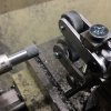
I started with a piece of 1.25" heavy wall 304 stainless pipe (Why stainless? Because it will genuinely heat-blue... No painting required), and turned it down to internal and external dimensions, put the three rings at the front in with a carbide 0.028 groover, and then turned it to length -or rather, what I thought was length, but I misread my blueprint and it's actually about 0.100" short. No big deal for the Mk.I version though, it'll be clarified on the blueprints and fixed in future. Then I clamped it inside two 1-2-3 blocks with a through-bolt, so I could index it 180 degrees for the vent spotting:

20161123_225901454_iOS.jpg

Yeah, no mill for me. Milling attachment in a lathe for the time being. It's... Super slow going. (Anyone for a Rey/Jyn-blaster let's-buy-Rob-a-mill kickstarter run? :p) I adjusted the hole spacing to still look appropriate on the slightly shortened barrel (0.012" less per spacing, iirc).

Because of that, I decided that drilling the holes once it was spotted could be done much faster in the drill press. It's a crappy drill press with plenty of vibration and runout, and I don't have any stub bits, so that was a mistake- the lines of holes aren't exactly linear. Nonetheless, onwards:

20161123_232532664_iOS.jpg

With some cleanup and adding the screw holes for connecting the barrel tip, it looked rather like this:

20161219_204544202_iOS.jpg

Next up was the barrel tip, which was cut fairly snugly (being burnt by over-frugality with materials has been a theme on this project; fortunately that wasn't the case on this part) from a length of solid 1-1/4" 304SS round. I cleaned up one end and turned a shoulder that fit fairly snugly inside the barrel tube ID, then flipped it around in the chuck to turn the exterior profile (the live center there is to help align it parallel with the chuck face, but with clearance from the jaws, using some shims):

20161119_014402386_iOS.jpg

No intervening images that I can find, so the end result, after drilling and tapping the M2 holes using the holes already drilled in the barrel tube as a guide, is thus:

20161219_204439160_iOS.jpg

That'll be held in place just by its mild friction fit and those screws.

Then it's a case of joining the barrel to the main body. The piece that will actually stick out of the main body looks like this at the front, drilled and tapped to M8-1.0:

20161219_204710434_iOS.jpg

The joining piece therefore has to be both the inner cylinder of the neck of the barrel, as well as the flat at the rear of the supression portion, and have enough surface area to glue to the barrel cylinder because there's no space there for any other method of joining (though, thinking about it, some very small dowel pins may not be the worst idea). Anyway, the result is this:

20161219_204624418_iOS.jpg

That's all the length it can have, or it would overlap the rearmost vent hole in the barrel cylinder. The fairly acute angle is to try to avoid reflecting very much light visible through the holes of the barrel. The flat, of course, is to take an M8-1.0 socket head cap screw:

20161219_204639009_iOS.jpg

That screws into the body like so:

20161219_204737726_iOS.jpg

Then I added an equivalent inset (by the thickness of the connector's widest point) chamfer and bore...

20161219_204604564_iOS.jpg

...So that it pretty much perfectly mates flush to the back of the barrel:

20161219_204813779_iOS.jpg

Given the heavy accumulation of dirt in that area, I doubt the difference between the aluminum and the stainless will be all that noticable. Of course, if I had a TIG welder, I'd have made the connector from stainless, welded it to the back of the barrel, and then re-turned that end. Alas, my Gear Acquisition Syndrome is incurable. As it is, alu is much easier to turn and it'll have to be epoxied anyway, so no big deal.

So, altogether, we have these parts (yes, I took these pics an hour ago, hence the completed side pieces):

20161219_204416176_iOS.jpg

Which together look like this:

20161124_031511539_iOS.jpg

By and large it's a little rough looking, but I've increasingly noticed that the actual prop is really very roughly built, so I'm not too concerned. So ends part three!
 
I like seeing metal work the old style, instead of todays everywhere printing. :)

When watching at your pics the first i did was wondering why you don´t use a rotary table

vertex003.png


But after reading the text i knew it. ;)

Still fun to look, i enjoy your way to work. :thumbsup
 
Ha, yeah; I own a rotary table, but usable machining volume is a perennial problem for me right now. Once I get a little 4-jaw to go on it, instead of attempting to get the big vice on there, things like that muzzle become fairly trivial. But I'm trying to use the work itself to upgrade the facilities now- and become a net earner, in time- rather than simply ploughing money into it, so upgrades are fewer and farther between than they used to be. Thanks!
 
Nothing like losing 45 minutes worth of post writing to another tab crashing and autosave failing (and me not regularly select-all-copying like usual). Anyway...

Thanks guys! s2jesse, I read your NN-14 thread immediately prior to starting this one. Beautiful work. Nice toys, too. :D

This is gonna be a fairly bland update, just knocking out some stuff before the next exciting part. And I can't remember what all I typed, so there may be less detail this time around.

First up, the internal "chassis" bars:

I found a Dorian 2" indexable dovetail mill for like, $20, which due to the relatively light cuts I'm forced to take with the small machine, means I can happily use it as a facemill. So, first was to take the 3/4" bars and square and size them. The size they had to be was dictated by everything they interfaced with; they had to be large enough for everything to screw into them and for the grip to mate inside, but small enough that they didn't weaken the half rounds or prevent the end caps from screwing into those either. Ended up about 650 thou.

20161105_003745387_iOS.jpg

Then they could be thrown in the 4-jaw and the ends cleaned up and turned to length.

20161110_021945037_iOS.jpg

I didn't get the intermediate stages, but then the fronts were turned, drilled, bored, tapped, etc, and the backs were slotted. I didn't drill the sides yet, because I wanted the side panels themselves to be the drill guides for those holes.

20161114_000358104_iOS.jpg

There was a total-progress shot at the time. You can also see the trigger blank, which I was working on at the same time. Let's do that now too.

First I cut off a piece of 1/4x1-1/4" 304 stainless bar. I used 304 for everything because I'm a masochist, I guess. I wanted all the parts that would be interacted with regularly to be stainless, but I'm drawing the line at the safety because I'm not about to attempt to knurl 304 rod on my machine!

20161107_141227655_iOS.jpg

Just a case of facing off the sides. I'd have taken it down to size in the mill, but at this point I was still thinking that the grip laminations were 3mm apiece rather than 2.5mm, because I hadn't double checked my own model measurements.

20161108_165015724_iOS.jpg

(There's the internal bars at length but prior to shaping)

The top and rear of the trigger was fairly simple and could be laid out normally, but the weird compound curves at the front I decided would be much easier to just template. So I made a Monster Clay version of the front half from a 1:1 blueprint.

20161117_212038505_iOS.jpg

That was transferred to the trigger blank with spray paint, but since both the Dykem and paint did pretty badly dealing with the heat buildup from cutting and grinding (hours and hours of tedium!) I ended up going over the lines with a scribe.

20161122_021906901_iOS.jpg

After a couple days of grinding, filing and hand sanding, including taking down most of the visible milling marks and reducing the width by that pesky 1mm (couldn't really hold the flats to a bench sander, sadly), it looked somewhat like this:

20161224_182430180_iOS.jpg

That's the end of that. Good riddance! :D
 
Last edited by a moderator:
Ok, now for the "real" update: the half-rounds! This is where it starts getting exciting. Of course, this was also the longest, most intricate and also most wasteful part of the entire build.

The idea was fairly simple. Instead of turning a solid round, then splitting it- which by definition would not produce semicircular prisms, as it were- I decided to go the opposite route- buy 1:2 aspect ratio stock (in this case, 3/4x1.5" 6061-T6511), facemill one side so that two pieces meet uniformly, and then turn the entire unit as one.

20161113_233518315_iOS.jpg

Obviously, there were problems with this idea- the faces had to be very smooth, fairly perfectly square to the extruded faces (in order to be chucked up and dialled in), exactly the same thickness after facing off (so that the mating plane would remain centered after indicating in), etc.

Initially I tried to do this with the two pieces separate and already almost to final length, so they could just be flipped around in the chuck, but trying to realign two un-keyed parts didn't go so well.

20161114_012338033_iOS.jpg

So, a couple feet of wasted material later, I decided it was a false economy and to suck it up and lose an extra couple inches per part in order to maintain alignment. So, I got some more material and cut it to about 5 inches instead of the ~3" that the body core is, and set about facemilling and manually lapping the faces (only to about 400 grit though, that's good enough) all over again. It takes a couple hours per piece, because you're trying as hard as possible to maintain even pressure and a consistent arm angle to minimise loss of parallelism.

Once I'd finally ground them all flat and brought them to within (as I recall) about 0.002" of each other in thickness, I milled a pocket in the center of each one, that would become the slot for the chassis bars. This slot is fairly critical, since the depth of it controls the axis of the bars, which is in turn the axis of the barrel and front knob thingy, which have to also interface with the front end cap. Side to side motion isn't the end of the world, since the bars will be held in place with screws anyway, but as close as possible is better, especially for turning since the slots would need to be aligned far more than the outsides of the stock.

20161128_195322353_iOS.jpg

This was a total-progress shot at the time (I machined the sides while the lathe was still in mill-mode, before turning the half-rounds- it's a lot of effort to switch back and forth):

20161130_160257132_iOS.jpg

So I aligned the slots with each other by just putting the actual chassis bars inside them, and then drilled, counterbored and tapped each part so that they could be screwed together.

20161206_203522422_iOS.jpg

Then it was just a case of turning them round and taking them to diameter:

20161206_224756836_iOS.jpg

And, thanks to those "waste" tabs, the whole thing could be turned at once:

20161207_025725495_iOS.jpg

Then we can crack open the egg to see what we've got! (I guess those screws won't be getting used on the final product, eh?!)

20161214_171524590_iOS.jpg

Magic! Ain't she purdy?

20161214_171826538_iOS.jpg

...I was so happy at this point. Huge relief. Now I just had to not screw up getting the tabs off.

20161214_174819669_iOS.jpg

Going strong! Finally starting to look like a real thing, at last.
 
What method are you using to get the square on the side plate "square"? Or are the corners going to stay rounded?
It's looking great!
 
Thanks everyone! :D

Side scale update, now that I have them finished! Not super thrilled with these, but that's what v.2s are for, right?!

Started with a sheet of quarter inch 6061 plate, cut to near-size.

20161115_154854216_iOS.jpg

These were ground to uniformity on one side and the edges milled to dimension.

20161122_221252271_iOS.jpg

After destroying the cheap Indian-made (even worse than Chinese-made, when it comes to steel goods- though not food! :thumbsup) Grizzly slitting saw, along with its arbor, somehow (the screw just ain't coming back out, for whatever reason), I got a nice US made saw and rustled up something resembling an arbor:

20161123_182632373_iOS.jpg

Not exactly concentric, but I'll work on the design in future- I had work to do!

It still came out generally fine:

20161129_194446015_iOS.jpg

Then came the square. Apparently I didn't get any photos of the process, but it was fairly straightforward. Since the corners need to be as square as possible, the optimal machining bit is the smallest one on hand. In this case, a 1.5mm drill bit, since I don't generally use tiny end mills. I'd have gone smaller if I'd had something. Drill a hole one radius in from the corner in x and y, so the hole is just touching the outline on each side. Repeat for all four corners.

Then come in with a bit about twice as big, and do the same thing (a 1/8" bit for me, I think). Finally come in with the biggest bit you intend to use, which is essentially whichever bit you have that's large enough to get your smallest square or triangle file into the diagonal egg-shaped hole you've now made. Then mill out the main body of the square with a regular end mill to whatever depth you're aiming for. Then, if all has gone to plan, you can file the corners into squareness (because you went all the way through there to get the file in).

20161214_174819669_iOS.jpg

For me, there was chatter and drift on the milling portion of the operation, and the hole ended up less than perfectly square. Definitely something that'll get fixed for v.2 (by using an actual mill rather than a lathe milling attachment!) Still, it's not too terrible for the time being. I then thoroughly scratched up the inside of the square with the point of a needle file for later.

Next, countersink the back of the holes...

20170109_221423622_iOS.jpg

...And aluminum tape them up, so...

20170109_222818882_iOS.jpg

...We can pour Onyx in the front to form the black bit!

20170116_192112491_iOS.jpg

Just barely scraped hitting the tail end of the pot life on that, after pouring new scales! Onyx SLOW is actually pretty fast. Fortunately I was just quick enough to give it time to find its level. The front line bits were too late and peeled back off.

20170116_192424335_iOS.jpg

Then just a case of knocking it back down with the Dremel...

20170117_154458932_iOS.jpg

...And filing it into some squareness before smoothing it out up to 220 grit (the black square in the movie is fairly matte compared to the grip, though it might be a touch higher than this). The lack of squareness looks more like weathering here, so maybe between the generally rough finish and heavy weathering overall, it shouldn't be too obvious.

20170117_175401224_iOS.jpg

Currently working through the list of final things to do, so there should be a few more updates this month!
 
Another chunky update today for the safety selector! This might be my favourite part on this thing.

First I had to make a custom knurling tool because the knurling on the selector doesn't appear to be a simple 1:1 ratio diamond pattern:

20161213_010227020_iOS 1.jpg

This worked nicely, though I overcooked it a touch on the compression; of course coarser knurls have deeper grooves, so the fine lines were drowned out a little. Just something to be more careful of on v.2!

20170106_151341050_iOS.jpg

Next I did the layout on the top cover, roughly cut it to size, and drilled the two screw holes. That way, I could fairly easily mill flat the sides using the 3mm drill bits as dowel pins:

20170107_010748771_iOS.jpg

Then it was just a case of rounding the ends, using the milled edges as reference. I did it by hand, and I think it actually came out fairly decent:

20170107_015947763_iOS.jpg

A little slotting and it gets a whole lot more recognisable! The safety actually isn't visible in this scene on Takodana, sadly; nor is it actually evidence that Rey "turning it off" is anything other than a sound effect, from what I see. Not good enough for my builds!

20170107_181432375_iOS.jpg

Drilling and tapping the main grip body to take the safety plate (very carefully!):

20170107_235437572_iOS.jpg

And the results. The tap got pretty unhappy at this point, and I'm running low on M3 taps, so I wasn't gonna push it, even though ironically this is the one operation on the entire thing where breaking a tap really wouldn't matter!.

20170108_001850514_iOS.jpg

Turned out that 1/4x1.5" aluminum bar was just the right size to fit under the cover, so I surfaced it to 5mm, put some shoulders in it, and slotted the mechanism area, which was sized according to the size of the magnets I was planning on using, basically (also 5mm diameter). Then it was a case of figuring out exactly where the base could go in the grip body, based on the fact that I was planning on securing it with the double M2 screws.

20170115_202924015_iOS.jpg

That was easy enough to cut out, as it happened; just line up a parallel with the line you're trying to cut to, clamp it on, and use it to align the part in the vise. I'd envisioned something much less fun.

20170115_210321251_iOS.jpg

Round off the corner, some filing to fit, drill the screw holes, and it's good to go.

20170116_000105598_iOS.jpg

All that was left was to drill and tap the hole in the knob itself, which was disconcerting because it's so thin an area, but it went ok.

20170117_012640056_iOS.jpg

Then it's done! Looks like so:

20170117_030635699_iOS.jpg

20170117_030846784_iOS.jpg

The little connector doohickey I guess was so fast to make I didn't get to take any pics, but it's pretty obvious how it works, I hope!

All for now.

Edit: Oh! A video of it working would be nice, eh?! Clickety clicking is here: https://twitter.com/robtaylorcase/status/821202966858395648
 
Final "full" update on this thing, I think! Still some miscellaneous stuff to add at the end, but this is the end of the build journey proper. Of course, it's still sitting in pieces on my desk here because commissions come first, so it might be later this week before I get it assembled and final images shot anyway!

Final round of grip construction images!

First I had to rebuild the failed grip holder, as explained above, so I came up with the easiest way of doing it with the materials on hand:

20161103_020439318_iOS.jpg

...Which turned out fine, using a Kant Twist as the fourth wall.

20161104_194607110_iOS.jpg

Then, after deciding that doing a big measurement and layout job was really way overkill for this, I printed a new version of the grip frame blueprint at 100% scale with some extra landmarks, and contact cemented it onto the first plate. Then I could start drilling and tapping the plates using it so I could screw them together for the rest of the process.

20161215_231149163_iOS.jpg

At a certain point, experience will kick in and tell you that something that should be fine could potentially go horribly wrong. So I punched the outlines in case the paper got wet, covered in oil, scraped off, rubbed off, burnt off, etc etc. I'd still have something to work to without having to perfectly line up a second template to a half-finished job (that would likely be slightly distorted from a fresh version because paper moves as you work it):

20161215_231741948_iOS.jpg

After roughly cutting it out with a bandsaw, it was time for a ton of filework:

20161217_164630049_iOS.jpg

The dremel and jigsaw came out to help a little bit here and there, too. The Dremel general purpose carbide cutter is actually really nice for this work, as long as you work around the fact that it'll like to periodically dig in on you, and send razor-sharp aluminum needles pretty much everywhere. It's like working with fiberglass insulation.

20161218_172141442_iOS.jpg

Yes, I know I need a bench vice. :D

20161220_011600357_iOS.jpg

Mostly there! Now just for the fitting at the front, and all the little details.

20161220_022150647_iOS.jpg

To put the trigger in, I just set it on its screw pivot and sketched around the top to get its general circumscribed outline. That was cut out, along with the hole for the nearby screw, and they were joined up with a channel.

20161220_152912182_iOS.jpg

Since I recast the grips for the side panels' black square to avoid resin waste, I finally decided to stop procrastinating on that. First I sanded the backs just-under-flush, so that the rim could be easily dialled in to exact depth with a file (I over-poured them this time. More cleanup, but more precision).

20170116_221401079_iOS.jpg

Then I clamped one on the grip frame after measuring and drilling their holes from the original 3D model I built, and transferred those holes with the screws (screw against the flat to leave a ring imprint) and drill bit (just twizzle it through against the grip, and you'll get a drill spot in the center of your inscribed circle). Drilled that one grip using the magical grip-holder jig, and transferred the points using this highly conventional technique:

20170117_025855779_iOS.jpg

Drilled the second grip, then counterbored both of them, using another set of measurements from the original 3D model, by using the 3mm drill bit as a dowel pin (again!) to align the spindle.

Finally I made the spring for the trigger using- if I recall correctly- 0.025" piano wire, I wanted it to have some tension. Tested and adjusted it as I went, and voilá!

20170118_184453789_iOS.jpg

At this point in the process, basically everything's done. I'll get the final miscellaneous update up in the next day or so, and then hopefully shortly after that we can have some pretty final pics!
 
This thread is more than 6 years old.

Your message may be considered spam for the following reasons:

  1. This thread hasn't been active in some time. A new post in this thread might not contribute constructively to this discussion after so long.
If you wish to reply despite these issues, check the box below before replying.
Be aware that malicious compliance may result in more severe penalties.
Back
Top