Y-wing... Why Not... SS Y-wing Build by mjhenks.

Sometimes you have to take steps backwards to go forward. Or admit you did not plan this right and do it over again. Same thing right??

As stated last week i decided not to use 9V batteries in this model. I want to use 110V. How do you get that into the model and be able to disconnect it?

How about using a 3.5mm audio jack. That is what i used on My R2D2 to power the dome so we will do the same here.

IMG_7327.JPG


The rod machined up to slide into the Body and the base.

IMG_7333.JPG


The going backwards part. I need a hole from the body mount into the body cavity. For this i drilled a 1/2" hole through the center of the 5/8" body mount, through the plexy wing spar and into the top cavity in the body. I also drilled a 3/16" hole through the center of the aluminum wing spar from the rear into that same cavity. A flashlight shows that they connect.

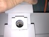
This allows me to epoxy the 3.5mm receptical (Harvested from a old CD ROM drive) into the body and have the wires go back to rear of the body (where the 9V battery would have been) to connect everything together.

While doing this i got a huge cracking sound too. That can't be good...

IMG_7329.JPG


IMG_7331.JPG


I have some body work to do.

IMG_7332.JPG


I learned that Nurnies are shipping so by the time they arrive i need to have this all fixed.
 
Received some goodies.

Some super nice decals made by moffeaton from his thread found here. Decals sheet update for 2020

They are for the Y-wing, X-wing and Tie so i hit a home run for all three of my SS models.

IMG_7345.JPG


Some new vintage Leggs to remake my nose cones arrived.

Did not realize there was an intermediate style of a half egg. (Left) The profile looks the same so i think i am good here.

IMG_7344.JPG


Finished the power entry connections. I ended up drilling a 1/2" hole down the center of the 5/8" post hole all the way to the inside top of the model. That is how i cracked out the top originally.

I had to go get the rest of the material out and further cracked it last night. No big deal. Easy to fix.

IMG_7342.JPG


I made a wood adapter for the 3.5mm receptacle. This centered the plug in the 1/2" hole and helped glue it in place. After wiring it up i used JB weld to glue it all together.

To place the receptacle i applied the glue and then attached it to the post. Using the post i set it in the 5/8" hole to set the spacing while the glue cured. I checked it every once in a while to make sure i was not gluing the post into the model. It worked out great.

IMG_7336.JPG


IMG_7340.JPG


IMG_7343.JPG


Next step is to finish the wiring and i am cooking up a sound module idea.
 

Attachments

  • IMG_7341.JPG
    IMG_7341.JPG
    1.9 MB · Views: 107
I have often said "Sometimes one must take a step back so they can take two steps forward".

Love what you have done with the support/power supply. Your metal working skills are phenomenal.
No worries on the battle damage either. Most of it will never be seen.
 
OK. Not electronics like i thought. I do have a USB programmable sound module on order and have been working on my engine lights. Unfortunate though that i blew both of my flashlight LED's. One of the driver boards and one CREE LED testing @ 12vdc. I learned a few things so that is OK. New solution is on the way.

I started working on replacement engine domes instead.

I thought i would work with the intermediate Legg's to see how they would work out. I liked the idea of being able to chuck them up in the lathe using the cylindrical back side. Well it worked but they are super thin. Once i was done one cracked in half. Easy to fix but SUPER thin! I ended up turning them to size by using my x-acto blade as a parting tool while the lathe spun the part.

IMG_7347.JPG


IMG_7352.JPG


I was not happy with the domes i did a few months ago where i filled the entire inside with Bondo and turned a step in the bondo. It was messy and requred me to be creative in how i held the dome in the lathe.

This time i turned a wood disc seperate and placed it on top of the bondo as it cured in the egg. By setting thing level, filling the egg leaving about 1/4" from the top unfilled and centering the disc in the bondo i came out with a nice filled egg and a round boss on the back side.

IMG_7348.JPG


IMG_7351.JPG


IMG_7354.JPG


Now to trim the mating face so it sits flush with the motor.

I mounted a spray paint cap in the lathe with the open side outward. I then used the tool post holder to press the egg into the cap so that the tool post holder kept the wood flat in the egg perpendicular to the spindle. Then i taped the egg and cap together giving me a way to spin the egg from the nose side. Using a small lathe tool i hand dressed the mating surface and using a cut-off tool squared things up. Worked great.

IMG_7359.JPG


Next off to do body work and clean up the dome. The one that cracked had a seam once i glued it back together. Had to dress that up with some spot filler putty.

IMG_7356.JPG


New armor plates were made. Cut these 1mm oversize on all edges. Stacked them up and clamped them together. Put them in the mill and squared up all four sides then cut the 45 degree chamfer. The results are 16 pieces of armor all pretty much the same size. Will mount them this weekend and finish the domes.

IMG_7360.JPG


At this point i am in a holding pattern waiting for electrical and detail parts. I do have some of the engine nurnies in hand but do not want to mount them until i have everything.
 
Finished electrical testing on the lights. Have not put connectors on them but have all lights now working off of one circuit. I switched to 9V instead of 12V to cut down a little on the brightness and heat generation. (Also because my 12V wall wart died and 9V is what i have.)

I machined down the flashlight housings to fit the back of the engine pods, wired it all up and ran it for 30 minutes to make sure things did not get too hot. Worked fine. Next step is connectors and proper wire lengths and then stuff it all inside.

The last two shots are with and without flash.

Question.

Was thinking. Were there any lights on the body of the Y-wings? Seems to me that the Astromech for sure but normally there are lights all over the body of a craft. Engines and running lights. I know it is a movie and i know for instance the models probably never had engine or cockpit lights but thought i would ask.


IMG_7384.JPG


IMG_7385.JPG


IMG_7396.JPG


IMG_7397.JPG
 
Today's update includes more wiring, cockpit mounting, nose cone's and R2D2.

Final testing of the entire electrical system before installing it went well. No issues. Everything has a connector.
Lets stuff it all inside and see if it still works.

IMG_7403.JPG


IMG_7402.JPG


IMG_7406.JPG


Time to attach the cockpit and make sure it all fits.

I found that i messed up the fiber optic light unit mounting. They interfered with the torpedo launchers and the cockpit upper body brim. I had to re-locate the LED units and trim both the upper cockpit brim and torpedo tubes. No big deal.

My game plan is to put the cockpit halves together, mount that to the armature and then insert the cockpit into the socket for final assy. That may allow me to paint the body with the cockpit not installed. We will see. Painting still sort of freaks me out.

IMG_7416.JPG


IMG_7418.JPG


IMG_7421.JPG


IMG_7424.JPG


I realize at one point i was thinking Red Jammer. I like the red color. Nothing more. The problem is i own a real R2D2. My ships has to have an R2 unit. I guess that means i am building another ship or doing my own thing. Not sure what yet but i needed an R2 unit and he has to light up.

I ran two sets of wires into the cockpit area so one will be for R2. Not enough room in there for fiber optics so i drilled out all the holes in the dome and stuck into the body all three of my flicker LED light units. (Red, Blue & White) I had to bore out the body using the lathe. Talk about pucker factor.

The LED lights randomly light up the dome which is pretty realistic. The first tests had too much light coming through the resin body. The last test is with the inside of the body and dome painted flat black.

IMG_7426.JPG


IMG_7430.JPG


IMG_7428.JPG


IMG_7429.JPG


Time to finish my new nose cones. Profile is alot better this time with that angled look which seems wrong from a real ship design point of view but right for the model. New armor applied. Honestly i am not pleased still. The armor just does not look right to me. Not sure why...

IMG_7431.JPG


IMG_7432.JPG


Patiently waiting for Nurnies. Next is mounting the nose cones and struts but wanted to hold off as long as possible.

I am a bit confused on the engine pod right now. It seems like there are additional panels harvested from the Saturn V that are overlaid on top of the main Saturn V engine pods as part of the detail work. Any guidance there???
 
ANH Y-Wing Engines.png

Here's a shot of Gold Leader's engines from ANH, the original edition. I thought the lights might be pulsating, but they're actually steady, red lights.

Here's another shot:
ANH Y-Wings.png

I think one of the red disks must have fallen out of the engine on the far right. :p

And here's a close of the black/silver R2:
ANH Y-Wing Black Silver R2.png
 
"Look at the size of that thing."

Some famous quote from some 2 bit actor. ;)

I feel kind of silly admitting this but i really had no idea how big this model was when i started it. I was thinking Kenner Y-wing for whatever reason. As i am going along i am figuring it out. I was playing around last night and fit one set of T bars and fins and how. Big model.

I am also taking a ride down memory lane with these Nurnies. I spend untold hours as a youth building models. Mostly Tamiya military and Hasegawa planes. It is really fun to recognize parts. I also have a deep appreciations (and respect) now for you crazy guy's who collect all these parts. :)

Anyways. Nothing new here and nothing more.

IMG_7447.JPG
 

Your message may be considered spam for the following reasons:

If you wish to reply despite these issues, check the box below before replying.
Be aware that malicious compliance may result in more severe penalties.
Back
Top