Y-Wing (Gold Leader) Build - Nice-N Model Designs

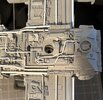
While going through my reference photos, I came across a pipe that I had originally missed (below, center) on the starboard/right side. I thought this one was interesting because it appears in the production photos, but not in the post-production photos, including the museum pictures.


IMG_3542.JPG

Also interesting is that it appears to be inserted into the same part as seen on the other side (port), lining up exactly with the corresponding pipe:

IMG_3543.JPG

I'm guessing that the original pipe fell off the model at some point. It's a little surprising considering the fact that there are plenty of other more fragile parts that could have fallen off or even broken off instead.
Well, I'm out of time this weekend. More stuff to come next week. ;)
 
While cleaning up the seams on the engines, I noticed that the detailing (patch panels) on the front of the wings was wrong. Here's a before photo:

IMG_3547.JPG

There's no detailing on the right side and the detailing on the left side is incorrect. Here's a closeup of the right side:

IMG_3548.JPG

More than likely, this is correct for Red Leader. I've removed the detailing with an X-acto knife and some 220 and 600 grit.
The patch panels look like they are all about 1/16" wide, so they're easy enough to cut out. I've already cut them out of some styrene. I just need to clean up the area before applying them.

And here's the finished product. Left side:


IMG_3681.JPG

Right side:
IMG_3682.JPG
 
Last edited:
We had a heat wave recently so instead of bending plastic rods for the "pipes", I decided to add some detail to the main engines. Here's a before shot of the left side:


IMG_3669.JPG

Before gluing the panel, I held it in place and then used a heat gun to help bend it so that it would lay down properly:

IMG_3670.JPG

And then on to the right side. Same technique:


IMG_3671.JPG

While looking at the reference photos, I noticed that the right engine was missing some pipping detail near the top:


IMG_3673.JPG

The detail is so small that it didn't get pulled during the casting process, which is typical. At first I thought it was a very small piece of round rod, but it turned out to be the same material used for the patch panels. I used another, similar piece of detail as a reference for size:


IMG_3672.JPG

I trimmed a small piece and then sanded one side with 220. The placement was tricky. Super glue was applied on both ends and then a little near the center of the piece on the engine only. One end of the piece was held in place until it was dry and then the other end was held in place:

IMG_3674.JPG
 
We had another heatwave this past weekend, so I decided to stick with the engine detailing since there's still more to do. Here's a before shot of the starboard or right side:


IMG_3687.JPG

As with the other side of this engine, a small strip of styrene was missing along with a model part detail.
The good news is that the kit came with plenty of spare panel pieces, so I cut this detail from one of the spare parts:


IMG_3688.JPG

The part comes very close to the "T" track, so I double checked the placement just to be sure:

IMG_3689.JPG

At this point, the detailing for the tops of the engines is good, so I'm moving on to the undersides.
This is before shot of the port or left side:

IMG_3691.JPG

The "T" track actually fits between the two details. The fit wasn't exact and both of the details needed to be trimmed:

IMG_3690.JPG

IMG_3692.JPG

Another small, detailed model part needs to be placed right next to the "T" track. It just barely lines up with the detail below it:

IMG_3693.JPG

The smallest of the styrene rods used for the pipping gets placed right on top of the part. I really like this detail and prefer it over the flat, styrene used:

IMG_3694.JPG

At first I thought that was the last of the detail, but upon closer inspection, I realized that more pipping along with a patch panel was added, just next to the detail part:

IMG_3695.JPG

The pipping is the next size up. The patch panel may have been added as a way of ending the pipping detail.

I will be taking another look at the underside of the right engine because the detail on the left side does seem to mimic the right side (or vice versa), but so far I haven't found any good references of the bottom of the right side engine, so this may be it for the underside, engine detailing.

Up next, back to the pipping. :)
 
Last edited:
Moving on to the piping, this is the bottom of the left or port wing. This one is interesting because there is a medium size pipe that actually rests against the fuselage between two detail pieces. The pull wasn't perfect, so I had to clean it up a bit with an X-acto knife and some 220 gritt. I also had to remove the round, detail piece that was attached in the corner area (more on this later) in order to make sure that the pipe would fit properly:


IMG_3712.JPG

Here's the pipe in place. This one is tricky because it has to be bent twice. The final section of the pipe goes straight across the wing and into the left engine:

IMG_3713.JPG

The next couple of pipes are the largest of the bunch, which makes them more difficult to bend. I discovered that the trick to these is to heat the ends, then bend them up into the rectangular areas of the model part (I also made a small notch near the top of the pipes so that the end fits into the rectangular areas of the model part). Once that's done, they're bent at a slight angle, then bent again, going straight into the left engine. These pipes actually sit on and against the wing. It's tough to see from the reference photos but the pipe on the left is angled toward the wing where it rests:

IMG_3715.JPG

Here's another shot of them:

IMG_3716.JPG

There's a couple of small pipes that need to be added, along with the small, round model part and that should complete the left wing. More to come. :)
 
Last edited:
Continuing with the bottom of the Port/Left wing, I've added the small pipe (smallest size of all the rods needed) which sits straight, on the wing. Unfortunately, it's very hard to tell from the reference photos, but the large pipe that sits right next to it is actually tilted:

IMG_3725.JPG

Now that the pipes are in place, I can put back the small, round model part. It turns out that I had originally attached it using the wrong side, so I've placed it correctly, this time. Just a tiny bit of material was removed from the fuselage and the part itself to help seat it so that it's mostly flush with the fuselage area:

IMG_3726.JPG

Here's another shot of the same area:

IMG_3727.JPG

Up next, installing pipes on the bottom of the starboard/right wing.
 
Last edited:
The pipes, the pipes are calling...

I love getting to the pipe stage -- this is the element that "pulls it all together" and makes it look like the stripped-down hot rod it was meant to be.

Lovely stuff, thanks for the pictures.
 
For the bottom, starboard/right side, I simply added the same three pipes toward the rear of the wing that were on the port/left side.
A nice, straight pipe was added toward the front of the wing, which was basically mirrored on the port/left side.

After double-checking reference photos of the bottom, I noticed one last pipe that needed to be added near the starboard side. This pipe is the smallest size. I used a round marking as a reference for placement and bent the end of the pipe, then shortened it. Here's what it looks like before placement:

IMG_3742.JPG

I was a little surprised that another pipe wasn't added to the port side, but a small, detailed part was added instead.

Here's a nice side shot of the pipe in place:

IMG_3744.JPG

Here's a nice overview shot of the bottom with the final pipe in place:
IMG_3743.JPG

So that completes the pipes on the main fuselage and the wings. There are some additional pipes that needed to be added between the forward and main fuselage, otherwise known as the "neck" area, so that means it's time to mount the forward fuselage or cockpit.

Before I do this, I want to make sure that the forward blaster guns are mounted properly. From what I'm seeing, they are sticking out properly, but the bottom portion of the fuselage may be too long, so I'll have to trim it:

IMG_3745.JPG
 
Before installing the forward section, I double checked the Red Leader instructions (since the Golder Leader instructions are missing this step) and realized that this set of parts will need to be assembled before finally connecting the section to the neck area. At the very least, this will give me a longer break before continuing with the pipes. :)

I have installed the blaster guns so now it's time to trim the edge of the bottom panel. I checked the reference photo. About 3/32" of material needs to be removed. This will help to expose more of the blaster gun details.
I used a set of calipers to mark the edge to where it needs to be trimmed:

IMG_3758.JPG

I used a large X-acto knife to remove the material and then a sanding belt to clean it up a bit.

Here is the cockpit with the bottom trimmed and cleaned up:


IMG_3759.JPG

I've attached the back panel with some contact cement and super glue. I want to make sure that it's in place, permanently before attaching the bottom panel.
As a side note, in this shot, the blaster gun installation is easier to see. Because one of them was too short, I used a small wood screw with a washer to help keep it in place. The other gun was simply glued in with contact cement:


IMG_3760.JPG

Next up, finishing the cockpit assembly and cleaning up the seams with primer and puddy.
 
I was lucky enough to get the day off for the holiday yesterday, so I finished the assembly with a little contact cement along the edges and inside of the forward section. I had a hard time using clamps, so I used some super glue along the edges to help keep them in place:

IMG_3761.JPG

After letting it set for several hours, I went back and filled in the crevasses with Tamiya Modeler's putty:

IMG_3764.JPG

Up next will be the usual paint/sand/putty, repeat process and then the final installation. :)
 
While waiting for the putty to dry on the cockpit section, I decided to move forward with a final part near the tail end of the main fuselage. This is an interesting part because it was missed in the instructions and it's also missing from at least one of the reference photos, but I found it here while working on the pipping about a month ago:

Top - Right Wing.jpg


It looks a lot like this part, which looks a lot like a lower control arm from a car:


IMG_3793.JPG IMG_3792.JPG

Unfortunately, only one of these parts is included in the kit, so in order to get another one, I decide to simply make a mold of just a section of it. I had some other molds that I needed to make recently, so I made this one at the same time. Here's the copy I made:

IMG_3844.JPG

After a little trimming, here's the part in place along with the original part:

IMG_3846.JPG

I'm not 100% sure that this is the correct part, but the proportions are definitely correct, partially because it does fit right under the pipe.
Here's another shot of the parts in place:

IMG_3847.JPG

With the last of the main fuselage parts finally in place, I was able to install the last couple of pipes, which fit under the "lower control arm" part:

IMG_3847.JPG
 

Attachments

  • IMG_3857.JPG
    IMG_3857.JPG
    884.2 KB · Views: 81
After studying the reference photos, I realized that the edges of the forward fuselage are angled, so I spent the last several weeks applying puddy to the edges. After a lot of sanding and painting here are the results:


IMG_4296.JPG

One problem I ran into was that after applying several coats of primer, the panel lines started to fill up, so I used an X-acto knife saw or artists saw to help put the lines back and even add a few that were missing:

IMG_4297.JPG

IMG_4298.JPG

There was one line on the sides that wasn't necessary, so I filled that one in:

IMG_4299.JPG

For the most part, all of the lines on the left side matched the ones on the right.

This section still needs another shot of primer, but I'm going to wait until it's attached to the rest of the body, before applying any more primer.

Up next, attaching the forward section to the rest of the body, attaching the remaining, detailed parts to the bottom and the remaining pipes.
 
I followed the build instructions and attached the forward section upside down to make sure that both sections were aligned correctly. I used plenty of contact cement and a little super glue to quicken the process, although I still had to wait 15 minutes for the contact cement to harden enough to let go:

IMG_4302.JPG

Next up, connecting the switch and adding some final detail parts to the bottom of the forward section.
 
Thanks.
I think we're getting close to final assembly. If I can get all of the little details done by June, it will be a great time to start painting. :)

Now that the glue has hardened, it's time to attach the switch. There's a lot of left over wire and we only need enough to pull out the switch if it ever needs to be replaced, so I take a quick measurement and then cut it down to a good length:


IMG_4309.JPG

Just as a reminder, this is the positive wire (in orange) that connects the positive ends of the two, LEDs to the positive end of the battery box. The wire is basically a loop that has been cut so that the switch can act as a "connector" between the lights and the battery.
I soldered the ends of the wires to the switch. From what is seen in the reference photos, the switch should be in the "off" position, so the terminal on the far right side and the center terminal are the correct ones to use. I tested the switch in the opposite position (left) and the lights work correctly, so we're in good shape:


IMG_4310.JPG

The wires fit in the hole I've hollowed out and the model part fits snuggly in place:

IMG_4311.JPG

The next part that goes into place is the fire extinguisher. I think the idea is to help cover the hole for the switch:

IMG_4314.JPG

Now it's time to add the "mystery" part that appears to help keep the switch piece in place. I went through a box of spare parts and found what looks like an oil pan model kit part that was left over from some ROTJ Boushh parts. It's exact length and width needed, but it's missing some details:

IMG_4312.JPG

The part is trimmed all around and then the top section is milled down. I used an artist saw to add a line on the top and then super glued a very thin piece of resin to one side. Once the glue has dried completely, I'll clean up the piece a bit and then prep it for painting:

IMG_4313.JPG

Next up, finishing up the neck area and attaching the final pipe pieces. :)
 
Last edited:

Your message may be considered spam for the following reasons:

If you wish to reply despite these issues, check the box below before replying.
Be aware that malicious compliance may result in more severe penalties.
Back
Top