The "leggs" domes went in quickly. The trick is to make sure that the detail is pointing inward:

Other side:

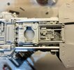
Full view:

Standing the model on its end, actually helps to keep the domes in place while drying.
Up next are the rear "guard rails". I had some trouble placing the left one due to the thickness of the detailed model kit part, so I removed it and milled/sanded it down a bit:

I thinned it out as much as possible:

Looking at the reference photos it's fairly clear that they used some "pins" of some sort to attach the pipes, so I'm going to use some small brads and a 1/16" drill bit to make holes in the pipes and on the model. I used the same technique on a BSG Viper Pilot helmet and some SW props in the past to help attach, small, resin parts:

It's tricky, but the pipes can be held in place with a standard, drilling clamp:

I used a belt sander to remove the heads off the brads. I suppose pieces of a large paper clip could also be used:

The narrow, model kit part gets put back with super glue and then I mark where the pipes need to go on the rear:

Other side:

With the brads in place on the ends of the guard rails, I double check where the holes need to be on the model. Once I know where to drill, I use a hole punch to create indentations:

I used a standard hand drill to make the holes on the model. The trick is to keep it level and as straight as possible:

The brads get super glued into the ends of the rear guard parts and then get installed:

I wasn't happy with my original guard rails, so I shortened them a bit so that they would align more with the details on the rear panel.
It's not difficult to remove the rear panel with the guards in place (and it probably won't get removed much, since its purpose is just to replace the battery), so I simply super glue them to the rear:

Up next, tacking the "T" rails and the engine thrusters.
")