Tron Legacy Costume

That sounds like a cold solder joint. Did the solder flow or just tack the wire on? Do you have any pictures?

Unfortunately no pictures. I will take a picture of my next attempt.

I am sure it is the result of my lack of soldering experience (pretty much none).

I put a little bead of solder on the copper soldering point on the LED strip and I tinned the wire. Then I put the tinned wire on top of the bead of solder and applied the iron. It seamed to hold nicely, but eventually cracked off.

I've done a few now and some seem to be on good and are not cracking off, but might with the right pressure.

Thanks.
 
That sounds like a cold solder joint. Did the solder flow or just tack the wire on? Do you have any pictures?
It might also just be a mismatch in the stiffness of the solder relative to the LED strip. Especially so if lead-free solder was used, as it is less ductile.
 
I only get to check in once in a while, but always know I can count on this thread to be flat-out awe-inspiring! I think I need to get back on the Flynn robes...
 
Hi All,

Just wanted to thank everyone who has worked on this thread at one time or another. After weeks of planing I have 95% completed my Tron Halloween costume. It's my first attempt at a custom costume for Halloween and although I'm really satisfied with the results, its also caused me a lot of blood, sweat & tears lol I've just got to modify my disc and touch up the black plastidip but its just about there. Thought I would post a few pics to show my progress.

prototype1.JPG


prototype2.JPG


prototype3.JPG


Thanks for the inspiration!
 
Quick update on my disc upgrade. I just got a pic from my friends shop. The disc is very smooth and has a bit of a glossy look. Almost like polished black steel. Its not what I intended, but I love it! I think it will look soooo slick reassembled. Ill rebuild it and post pics tonight! Almost ready!!

- Mister Digital

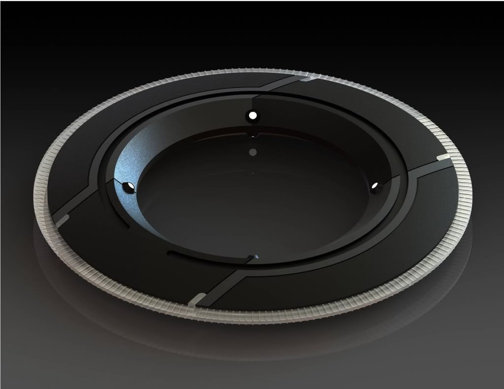
Nice work!:eek how were those made? Vacformed, cast? I'm working on a disc myself in a collaboration with TheMuffin. He's drawing up the CNC files and a friend of mine is going to do the job at his work. The pic is a rendering of of the slightly larger male vesion (9.25" diameter). It's not quite finished yet, but almost:

216e9810.jpg


Just out of interest, what were you going to use as the C ring and blade? I'm not sure which way to go myself. I might go to a gasket makers and get them to make the blades as I'd like mine to be a firm semitranslucent White rubber.
 
Unfortunately no pictures. I will take a picture of my next attempt.

I am sure it is the result of my lack of soldering experience (pretty much none).

I put a little bead of solder on the copper soldering point on the LED strip and I tinned the wire. Then I put the tinned wire on top of the bead of solder and applied the iron. It seamed to hold nicely, but eventually cracked off.

I've done a few now and some seem to be on good and are not cracking off, but might with the right pressure.

Thanks.

It does indeed sound like a cold solder joint. The proper way is to touch the tip of the soldering iron against both pieces that needs to be joined with as much surface area as you can from the iron itself. Now take the solder and touch the opposite side of the two pieces that need to be joined (solder not touching the iron!). This forces you to make sure both wires are hot enough before the solder melts and fuses to the metal.

You are actually using the heat transmitted into the wires to melt the solder. Not using the soldering iron to melt the solder directly. (although sometimes you take what you can get)

Yeah, I've watched a view youtube videos on soldering and I understand how to do it. I can solder two wires together using the method you described above with no problem.

But this is different than soldering two wires together. I need to solder one end of a wire to the little copper lead on the LED strip. How do I use your above method? How can I put the solder on the opposite side of these pieces?

Thanks for the advice.

Do you have a link so I can see what you're doing? I thought you were using light tape. The light tape I have is crimp style. I guess what I'm trying to say is I'm having trouble visualizing what you have in front of you.

Edit: I looked up what you're doing. It looks like you have to solder to the pads. Same method basically. Put the wire to the pad. Use the soldering iron to hold it down as you heat it up. Then take the solder and find a spot of metal (either pad or wire) where the iron is not touching. Wait until it melts and soaks it up. Push more soldering on to ensure there's plenty. Slowly let go of the iron being careful not to let the wire pull off as you move the hot iron from the molten solder.

If this works for you and you get a secure connection, place a dab of hot glue on it to help relieve some strain. Even better if you can hold the wire against the strip.
 
Last edited:
Do you have a link so I can see what you're doing? I thought you were using light tape. The light tape I have is crimp style. I guess what I'm trying to say is I'm having trouble visualizing what you have in front of you.

Edit: I looked up what you're doing. It looks like you have to solder to the pads. Same method basically. Put the wire to the pad. Use the soldering iron to hold it down as you heat it up. Then take the solder and find a spot of metal (either pad or wire) where the iron is not touching. Wait until it melts and soaks it up. Push more soldering on to ensure there's plenty. Slowly let go of the iron being careful not to let the wire pull off as you move the hot iron from the molten solder.

If this works for you and you get a secure connection, place a dab of hot glue on it to help relieve some strain. Even better if you can hold the wire against the strip.

So I shouldn't put a dab of solder on the copper soldering point on the LED strip ahead of time? The video I watched said to do so:

Soldering LED Strips - YouTube

You're saying to put the wire on the copper soldering part of the LED and hold it down with the soldering iron. Then touch a part of the wire that is not touching the iron and let the solder flow?

You can tin the copper, but it's not a dab. You heat it up enough to "paint" the copper area. I typically tin the wire, not the copper pad.

Correct. The idea again is to ensure everything is hot enough. Don't worry about fear of accidentally frying something as long as you stay on the pad. I have never fried anything using a soldering iron, nor has any of my coworkers. When you're doing it correctly it will instantly suck in the solder. You'll also notice a good section of the wire is quite hot, so be careful. Remember the wire will diffuse a good bit of heat, so that makes it even more difficult to heat up the tip and hold a hot wire still.

When you've done it correctly, even a very small pad and thin wire should be quite resilient from tearing off.

I don't agree with that video's method on that HUGE dab of solder on that pad. It makes it more difficult to tell if you have a cold solder joint. His solder tip is too big in that video also (not really a huge deal if that's all you have). Watching his solder joints, I can almost promise you those are all cold joints. Yes, they'll work. Yes, they'll conduct electricity, but it's a poor connection and easy to break like you've experienced. The wires won't get warm. At that length, they will get HOT.
 
^ Yeah, the video guy's technique is not very good. You can see that his solder joints look frosty white, which is another sign of a cold solder joint. If you want to use his method, tape down the wire too so that it rests on the LED strip's contact pad, then heat both with your iron and apply solder. This way the wire isn't trying to pull away from the LED strip as the solder cools.

A few of other thoughts.
(1) Use an iron with a smaller tip and lower wattage rating (30 W or so). Make sure the tip is clean and properly tinned (not burned, charred, and crappy like the one in the vid).
(2) Use thin wire (like magnet wire). If the wire's thinner, it will flex with the LED strip instead of trying to tear away as is the case with thick and stiff wire.
(3) When your connections are made, wrap some electrical tape around that end of the LED strip, covering up the contacts you've just made. This will help reinforce, protect, and prevent inadvertent shorts.

Ah, good point about the clean tip. Use a wet sponge to clean the tip with. Don't use the sponge to clean your dishes after.. it has lead in it. If you don't have one, you can use a folded wet paper towel. Typically I clean the tip, then lightly tin it. As I'm soldering, ill periodically white the tip off after a connection is made.

Also, if you have to solder such a short wire like he's doing, I like to use some needle nose pliers to do it. That way I can hold it there longer and when I pull away, I don't risk removing the connection before the solder hardens. If you remember, start off with a longer piece, then trim it before the other connection is made. That way, you damage the insulation less from the short wire heating up (as you can see the melted insulation in the video).
 
Hooking up the inverter that powers the light strip to the oscilloscope. I bought a 12VDC to 260VAC 800Hz one.

No load: 260VAC 1.37KHz @ 12VDC
With load: 260VAC 860Hz @ 12VDC

Quite impressed with the sine wave. I expected a really ugly square wave. Inverter weighs about as much as an apple.

317188_10100357431815829_25801449_50058479_1366439088_n.jpg


Test fitting the EL wire in a Disney Tron Disk. Added the diffuser back in. Was a little disappointed with the light output of the EL wire, but it will do. I'd rather not go thru the trouble of trying to cram a half dozen LEDs in there and a sizable battery. Still deciding whether or not to light the outer ring. Couldn't put it all together since I forgot my glue gun at work.

301908_10100357828790289_25801449_50060920_1363253893_n.jpg
 
Okay I'm super new to this site and to costume building in general.

I'm doing Kevin Flynn's black costume for halloween so it's much more simplified than what a lot of you guys are doing but I have some questions.

1. I can solder but I know nothing about electronics. How do I guage what I need to power this thing and how do I power this thing? I'll only have the one continuous strip probably.

2. Can I buy a kevin flynn style disk holder / disk somewhere?

I'm really confused on where to even start with the electronics.

Thanks!
 
Quite impressed with the sine wave. I expected a really ugly square wave. Inverter weighs about as much as an apple.
Wow...that is a clean sine-wave. Almost signal-generator quality.

Is the inverter from Luminous Film? The one I bought is rated for 12 VDC input and seems to be epoxy-potted in a square plastic shell. Still rigging up a set of cables and connectors today so I haven't fired it up yet.
 
Okay I'm super new to this site and to costume building in general.
1. I can solder but I know nothing about electronics. How do I guage what I need to power this thing and how do I power this thing? I'll only have the one continuous strip probably.

2. Can I buy a kevin flynn style disk holder / disk somewhere?

I'm really confused on where to even start with the electronics.

I'm new too, but I'm comfortable around electronics. I'd start off with what you want to accomplish and cost.

1. Are you going the light tape path? If yes, they rate it by square inches. So just calculate the length you have by the width. Then you can size an inverter and a battery pack.

2. I found mine on amazon. But I'm modifying it since I was unsatisfied that it didn't stay constant on. I found some impressive mods others have done on this forum after already starting mine.


Wow...that is a clean sine-wave. Almost signal-generator quality.

Is the inverter from Luminous Film? The one I bought is rated for 12 VDC input and seems to be epoxy-potted in a square plastic shell. Still rigging up a set of cables and connectors today so I haven't fired it up yet.

It's from Electro-LuminX Lighting Corporation. It does looks like what you describe. My coworker seems to think it's still a PWM with a good filter. I'm running almost 130sq in total, so I have the 50-150sq in rated one. It's about the size of my fist.
 
Last edited by a moderator:
Guys, big thanks for the soldering tips.

Working much better now. Only slight issue is being careful not to lift the wire up when removing the soldering iron, but not too big a deal.

Thanks again!
 
This thread is more than 3 years old.

Your message may be considered spam for the following reasons:

  1. This thread hasn't been active in some time. A new post in this thread might not contribute constructively to this discussion after so long.
If you wish to reply despite these issues, check the box below before replying.
Be aware that malicious compliance may result in more severe penalties.
Back
Top