Froggie
Well-Known Member
For the last few years I've had the idea of making an illuminating wand kicking about in my head. Looking around the internet I found a few creators who have done just this, and mixing their ideas and techniques set me on the path. Here's to giving back. I've tried to document this properly after that fact, as I didn't take the time while working.
My goals when setting out was to include a few features: to have it be made out of wood with as little visible damage to the grain as possible, replaceable electronics and a tip covered in thin veneer, all inside a body thin enough to fit the profile of the movie replicas.
Also the sun, the moon and the rainbow in a basket, please?
The idea of drilling out a dowel seemed bound to fail. Even if a drillbit would make it through without going out the side, the wood wall would be too thin and fragile to hold up. If I made the wall thicker there would be no room inside for the electronics, or the wand would be too bulky. This was the blockade that had me stuck for a long time in the planning phase, and it was sitting at a convention that I suddenly realized a possible solution.
Taking inspiration from bentwood ring tutorials, where wooden veneer is put on top of metal piping, I could theorically extend the structure to a hollow covered tube.
So I set about sourcing materials for my first prototype.

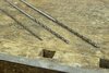
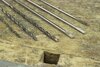
The battery is the least flexible part of the design, and I looked at many battery types before I settled on using a 8 mm diameter AAAA as the power source. Then I bought 0.5 mm walled brass tubing in RC shops, ranging from 4 to 9 mm outside diameter. Aiming for a 10 mm outer diameter at the thickest, this allowed me a covering of 0.5 mm veneer, which turned out surprisingly workeable.
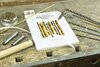
Looking for premade circuitry, I found plenty of arduino based prototyping boards available. None were even close to small enough to fit inside my required footprint, which on top of being a measly 7 mm wide was also round, so the effective headspace for any components was...limited. Still, I bought a few boards that had tiny components and simple layouts, because I had a plan...
A 3.3 V regulator, a capacitive touch sensor, a PNP transistor, a variety of bright 3x3 mm SMD LED's and a few variable regulators to test it all rounded out my materials list.
The most frustrating part of the early electronics was soldering the LED's, as the pads were so small and the bulb tended to overheat and burst from my shoddy work. My soldering probably improved a lot from doing this stuff, but I'm glad that I had the sense to buy lots of backups. Finally I got one to work, and it was easily strong enough to shine through the veneer I planned to put on top. The battery life suffered a bit, but I was having fun with it.
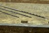
Moving onto the chassis, I cut, soldered and polished the brass piping into a stepped tube. Keeping it fairly straight was the hard part, as the small space between the pipe diameter was enough to make them go pretty wonky.
The brass pipes would also allow me to pull the ground through the wall itself instead of using a loose wire on the side of the battery, saving crucial extra space.

Next came fitting the electronics inside of the brass chassis. The PCB's were small, but a far cry from fitting inside my 7 mm inner diameter requirement. So, using a handy little hacksaw, I set to frankensteining my solution.

Marking up the components and creating a simple diagram of connections, I carefully took to sawing through PCB's, cutting them clean in half and trimming off the edges as much as possible with a dremel sanding drum.
After gluing the bisected boards in a straight-ish line, I then resoldered the broken connections back together. This was even more time consuming than the LED's, and the wires I used were far too big. Switching to thin winding wire later on helped solve the issue, but early on I had way too much material in the way.
After hours of work I had the circuit lighting up in its new, slimmed down form. Using winding wire I recreated the broken capacitive sensor coil in a footprint that would fit snugg against the chassis wall.
I now looked for a way to securely mount it inside the wand. I needed something that could act both as the positive battery pole, and also allow some kind of tool to hook onto it, to remove the circuit from inside the wand in a controlled way. I hoped for premade solutions, but nothing fit the bill or the footprint. This kind of had me stumped for a while, but in the end my dad suggested a bikewheel spoke nipple, and this worked out excellent.
After some grinding, gluing and soldering, the design had a working lower connector combined with anchoring point. More superglue on top of it ensured that it was isolated from the grounded wall, and it looked like my prototype was all set for its first test assembly.

Covering it in hot glue seemed like a good idea at the time, to provide insulation and give it a flexible press fit , but this turned out to be a major misstep.
This is also when I ran into my first major unseen issue: I had spent hours carefully making a circuit that fit inside the brass wand, only to find out that capacitive sensors don't work behind conductive materials. At all. The press fit was also far too tight, and the glue joint I had made was not strong enough, so the circuitry broke off inside of the wand. I had to use a fair bit of force to get it out, and then carefully repair it, now covered in thermal glue. Not fun.
After taking a frustrated break, I got back to work. If the problem was conductivity, then simply removing the piping over the sensor was of course the way to go. So my trusty hacksaw made a reappearance, helped along by a diamond wheel for the dremmel.
I also quickly made a battery ground plug out of brass tubing and a brass motherboard standoff screw, plus a top diffuser out of some acrylic rod.

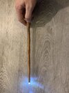
After assembling it all, the prototype lit up for the first time as a self contained unit, free from the breadboard.

This had me really excited. I had managed to fit all I needed inside. From here, I was sure that it would be smooth sailing, and that most of the really difficult work was behind me.
Oh boy....
So I started on plugging the sensor window. It couldn't be left open, since the veneer might break without a solid backing, and the coil inside might hook onto the wall and break, or get the circuit stuck again.
A plastic pen came to the rescue, and after some sawing and shaping, it provided a non conductive covering to the sensor.

Finally, I started work on the wood covering.
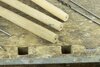
I used the same kind of technique that the bentwood ring makers do: boiling/steaming wooden veneer and then bending it around a similar size tube to dry overnight. This worked out well, although it proved difficult to get an easy bend onto the thinner piping without breaking it.

Having that done, sanded down the edges, and then set about glueing it to the brass using CA glue.
This was also time consuming and annoying work. As I had no jigg to hold it in place, I had to use my hands to keep pressure onto it as it dried. The thinnest part of the chassis was tricky yet manageble. It was when it came time to cover the steps between the thicker pipes that problems arose. I had covered the lower parts and sanded down a smooth curve, but the slight compound curves and not-quite-straight pipes caused the veneer to crack in several places as I applied it.
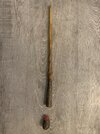
Not exactly a clean, untouched wooden finish, but I did manage to seal it up and puzzle it all toghether fairly well. After sanding, It actually looked like a wooden wand, although it was a bit thicker at the top than I had originally planned.
Still, it worked.


I finished this just in time for a convention. In fact, the last glueing was done while sitting and waiting at my table!
Driving back for 8 hours gave me a lot of time to think about my design, and I set out making a better one almost right away.
Repeating the same process with the second wand, I adjusted the top pipe thickness to be 4 mm OD instead of 5, to give it a more pointed look. The circuit also was far easier, as I had learned to use winding wire to save on space. CA glue insulated it and held it together more firmly than the hot glue from before.


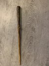
The second wand worked and looked far better overall, veneer transitioning more smoothly between the different layers and the circuit being more reliable.
Still, it also showed me the limitations of the current design and techniques.
For one, the work on each wand took way too long. One circuit board was almost a full day of soldering and glueing on its own, and although I likely could have gotten more efficient, the cost of the materials and likelihood of me messing up were way too high for my taste.
The second issue was the sensor. While the plastic window did work, it required precise measurements in creating each one, you had to insert it exactly right each time or it wouldn't function at all. It also made each wand circuit custom made for its chassis. On top of that, the veneer worked really well; well enough to make the sensor completely invisible from the outside, which might have been what I wanted, but it also made finding the activation spot very difficult unless you really knew what you were looking for.
Thirdly, the veneer application was really messy, and the result wasn't as nice as I had hoped. I'm sure that it could have been made better, if I practiced a lot and gave each wand enough time, but the concept was flawed from the beginning. It was clear that it would never give the finish I was aiming for, it limited me to wood types available in veneer, and it barred me from staining the woodgrain as the glue seams would leave blotches and show through.
The success did give me a platform to stand on, but it was time to go back and improve on the foundation of the core idea.
More on the way.
My goals when setting out was to include a few features: to have it be made out of wood with as little visible damage to the grain as possible, replaceable electronics and a tip covered in thin veneer, all inside a body thin enough to fit the profile of the movie replicas.
Also the sun, the moon and the rainbow in a basket, please?
The idea of drilling out a dowel seemed bound to fail. Even if a drillbit would make it through without going out the side, the wood wall would be too thin and fragile to hold up. If I made the wall thicker there would be no room inside for the electronics, or the wand would be too bulky. This was the blockade that had me stuck for a long time in the planning phase, and it was sitting at a convention that I suddenly realized a possible solution.
Taking inspiration from bentwood ring tutorials, where wooden veneer is put on top of metal piping, I could theorically extend the structure to a hollow covered tube.
So I set about sourcing materials for my first prototype.
The battery is the least flexible part of the design, and I looked at many battery types before I settled on using a 8 mm diameter AAAA as the power source. Then I bought 0.5 mm walled brass tubing in RC shops, ranging from 4 to 9 mm outside diameter. Aiming for a 10 mm outer diameter at the thickest, this allowed me a covering of 0.5 mm veneer, which turned out surprisingly workeable.
Looking for premade circuitry, I found plenty of arduino based prototyping boards available. None were even close to small enough to fit inside my required footprint, which on top of being a measly 7 mm wide was also round, so the effective headspace for any components was...limited. Still, I bought a few boards that had tiny components and simple layouts, because I had a plan...
A 3.3 V regulator, a capacitive touch sensor, a PNP transistor, a variety of bright 3x3 mm SMD LED's and a few variable regulators to test it all rounded out my materials list.
The most frustrating part of the early electronics was soldering the LED's, as the pads were so small and the bulb tended to overheat and burst from my shoddy work. My soldering probably improved a lot from doing this stuff, but I'm glad that I had the sense to buy lots of backups. Finally I got one to work, and it was easily strong enough to shine through the veneer I planned to put on top. The battery life suffered a bit, but I was having fun with it.
Moving onto the chassis, I cut, soldered and polished the brass piping into a stepped tube. Keeping it fairly straight was the hard part, as the small space between the pipe diameter was enough to make them go pretty wonky.
The brass pipes would also allow me to pull the ground through the wall itself instead of using a loose wire on the side of the battery, saving crucial extra space.
Next came fitting the electronics inside of the brass chassis. The PCB's were small, but a far cry from fitting inside my 7 mm inner diameter requirement. So, using a handy little hacksaw, I set to frankensteining my solution.
Marking up the components and creating a simple diagram of connections, I carefully took to sawing through PCB's, cutting them clean in half and trimming off the edges as much as possible with a dremel sanding drum.
After gluing the bisected boards in a straight-ish line, I then resoldered the broken connections back together. This was even more time consuming than the LED's, and the wires I used were far too big. Switching to thin winding wire later on helped solve the issue, but early on I had way too much material in the way.
After hours of work I had the circuit lighting up in its new, slimmed down form. Using winding wire I recreated the broken capacitive sensor coil in a footprint that would fit snugg against the chassis wall.
I now looked for a way to securely mount it inside the wand. I needed something that could act both as the positive battery pole, and also allow some kind of tool to hook onto it, to remove the circuit from inside the wand in a controlled way. I hoped for premade solutions, but nothing fit the bill or the footprint. This kind of had me stumped for a while, but in the end my dad suggested a bikewheel spoke nipple, and this worked out excellent.
After some grinding, gluing and soldering, the design had a working lower connector combined with anchoring point. More superglue on top of it ensured that it was isolated from the grounded wall, and it looked like my prototype was all set for its first test assembly.
Covering it in hot glue seemed like a good idea at the time, to provide insulation and give it a flexible press fit , but this turned out to be a major misstep.
This is also when I ran into my first major unseen issue: I had spent hours carefully making a circuit that fit inside the brass wand, only to find out that capacitive sensors don't work behind conductive materials. At all. The press fit was also far too tight, and the glue joint I had made was not strong enough, so the circuitry broke off inside of the wand. I had to use a fair bit of force to get it out, and then carefully repair it, now covered in thermal glue. Not fun.
After taking a frustrated break, I got back to work. If the problem was conductivity, then simply removing the piping over the sensor was of course the way to go. So my trusty hacksaw made a reappearance, helped along by a diamond wheel for the dremmel.
I also quickly made a battery ground plug out of brass tubing and a brass motherboard standoff screw, plus a top diffuser out of some acrylic rod.
After assembling it all, the prototype lit up for the first time as a self contained unit, free from the breadboard.
This had me really excited. I had managed to fit all I needed inside. From here, I was sure that it would be smooth sailing, and that most of the really difficult work was behind me.
Oh boy....
So I started on plugging the sensor window. It couldn't be left open, since the veneer might break without a solid backing, and the coil inside might hook onto the wall and break, or get the circuit stuck again.
A plastic pen came to the rescue, and after some sawing and shaping, it provided a non conductive covering to the sensor.
Finally, I started work on the wood covering.
I used the same kind of technique that the bentwood ring makers do: boiling/steaming wooden veneer and then bending it around a similar size tube to dry overnight. This worked out well, although it proved difficult to get an easy bend onto the thinner piping without breaking it.
Having that done, sanded down the edges, and then set about glueing it to the brass using CA glue.
This was also time consuming and annoying work. As I had no jigg to hold it in place, I had to use my hands to keep pressure onto it as it dried. The thinnest part of the chassis was tricky yet manageble. It was when it came time to cover the steps between the thicker pipes that problems arose. I had covered the lower parts and sanded down a smooth curve, but the slight compound curves and not-quite-straight pipes caused the veneer to crack in several places as I applied it.
Not exactly a clean, untouched wooden finish, but I did manage to seal it up and puzzle it all toghether fairly well. After sanding, It actually looked like a wooden wand, although it was a bit thicker at the top than I had originally planned.
Still, it worked.
I finished this just in time for a convention. In fact, the last glueing was done while sitting and waiting at my table!
Driving back for 8 hours gave me a lot of time to think about my design, and I set out making a better one almost right away.
Repeating the same process with the second wand, I adjusted the top pipe thickness to be 4 mm OD instead of 5, to give it a more pointed look. The circuit also was far easier, as I had learned to use winding wire to save on space. CA glue insulated it and held it together more firmly than the hot glue from before.
The second wand worked and looked far better overall, veneer transitioning more smoothly between the different layers and the circuit being more reliable.
Still, it also showed me the limitations of the current design and techniques.
For one, the work on each wand took way too long. One circuit board was almost a full day of soldering and glueing on its own, and although I likely could have gotten more efficient, the cost of the materials and likelihood of me messing up were way too high for my taste.
The second issue was the sensor. While the plastic window did work, it required precise measurements in creating each one, you had to insert it exactly right each time or it wouldn't function at all. It also made each wand circuit custom made for its chassis. On top of that, the veneer worked really well; well enough to make the sensor completely invisible from the outside, which might have been what I wanted, but it also made finding the activation spot very difficult unless you really knew what you were looking for.
Thirdly, the veneer application was really messy, and the result wasn't as nice as I had hoped. I'm sure that it could have been made better, if I practiced a lot and gave each wand enough time, but the concept was flawed from the beginning. It was clear that it would never give the finish I was aiming for, it limited me to wood types available in veneer, and it barred me from staining the woodgrain as the glue seams would leave blotches and show through.
The success did give me a platform to stand on, but it was time to go back and improve on the foundation of the core idea.
More on the way.
Last edited:
")