SS ANH TIE Fighter - some slight progress

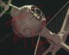
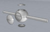
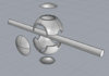
I'm pretty much done with the wing. You can't see it in my screenshot but both sides of the each wing are there.

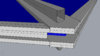
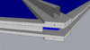
And, here's on of them questions that came up after all this. Now, keep in mind that I don't have good reference of a TIE from ANH. I couldn't get a good screen shot in Rhino so I drew the following by hand....not to scale of course.

So here are some of the layers. I'm coming up with a .060" empty area in between the wing star and the layer of Koolshade. The ABS H-beam #H-8 has a wall thickness of .060". So, do the wing stars sit on the H-beam? Or are the H-Beams cut at each intersection so the wing star arms can sit in between.

Cutting the H-beams at each intersection makes the most sense but without ref, I'm not sure if it is accurate.

Joe

IMG_20130225_183313_zpsc55df250.jpg
 
:( No bites, huh?

Well luckily I stumbled upon one great photo with just the answer I need. *Area in green circle* It looks like the H-Beams are trimmed at each intersection.

Gene, I borrowed your photo from the TIE-Spotting thread....lmk if you need me to take it down.

My new thought after looking at this pic concerns the thickness of the wing stars. If ILM used H-beams with a wall-thickness of .060" then it appears that the wing stars might be closer to .1" than .080".

LMK what you think.

Joe
 

Attachments

  • h-beamstudy.jpg
    h-beamstudy.jpg
    105 KB · Views: 298
  • .080.jpg
    .080.jpg
    187.8 KB · Views: 181
  • .10.jpg
    .10.jpg
    194 KB · Views: 165
Last edited:
Ok, I feel bad talking mad smack about my local cutter guy. I broke down and went back to him. Total 180°! I guess I caught him on his off day the first time. Bro-mancing aside, so I was finally able to get a wing star and hubs done! I'm so happy!

I only got one star done so that I could test the final measurements. It came out awesome! The beam took .007" off the edges but that is totally acceptable to me.
IMG_20130530_201208_zps2128a17f.jpg


I reworked the hub image so that I would only have to bend the slanted edges and glue in place. Unfortunately, the guy used .080" styrene. I asked for .040" but I wasn't mad about it. I am going to build a buck for a vac-formed piece so that I can decide on what looks and works best. I will have the other stars made here soon and then I can start the casting process of each donor part I will need multiples of. Not looking forward to that but it needs to get done.
IMG_20130530_201257_zps575b1646.jpg


Joe
 
So I started playing around with the cockpit. I'm trying to get a feel for how I will eventually cut into the 5.25" hemispheres.

The armature holes are going to be re-worked. The way they are now suggests that they will be drilled out. I am learning that will be more difficult that cutting them out the way I did the front and back window. That is, as if a miter saw was used to cut them out.

The top canopy and bottom hole are going to be tough, being as how my miter saw approach probably won't work there. Any suggestions are very welcome!

Joe
 

Attachments

  • tieball1.jpg
    tieball1.jpg
    184.7 KB · Views: 144
  • tieball2.jpg
    tieball2.jpg
    223.1 KB · Views: 134
Can someone help me confirm the diameter of the armature rod for the TIE? I've always read from 1-1/8" to 1-1/4". My rough estimation is 1-3/16". I'm hoping to have an aluminum armature machined using my drawings.

I also measured the window at 3.3". I just ordered the 5.25 hemis. I will start finalizing the measurements once I get them in. After that it's back to casting.

Joe
 
Last edited:
Small updates are better than no updates, wouldn't you say? That's why I never change the end of the thread title...LOL!

So, through trial and error, I finally settled on a styrene thickness for my hubs. They look great so far! I will need to add more parts to settle on the angle. Once I am happy, I will fill the edges and sand them down. The shape is symmetrical so not every part will match the filming model exactly in terms of placement. I'm still stoked, though!

tiehubs_zps0b97f869.jpg


Joe
 
Yes it does, Jason!

Can someone help me confirm the diameter of the armature rod for the TIE? I've always read from 1-1/8" to 1-1/4". My rough estimation is 1-3/16". I'm hoping to have an aluminum armature machined using my drawings.

And to quote myself, I'm still looking for assistance with the armature. I would totally appreciate the help!

Joe
 
Can someone help me confirm the diameter of the armature rod for the TIE? I've always read from 1-1/8" to 1-1/4". My rough estimation is 1-3/16". I'm hoping to have an aluminum armature machined using my drawings.

I also measured the window at 3.3". I just ordered the 5.25 hemis. I will start finalizing the measurements once I get them in. After that it's back to casting.

Joe

The Neisen kit is 1-1/8". The filming model is 1-1/4".

This is my best guess for the filming model (note, this will NOT work with the Neisen kit):

http://imaginager.com/drwg/master_1.png

http://imaginager.com/drwg/master_1a.pdf

http://imaginager.com/drwg/master_1b.pdf

http://imaginager.com/drwg/master_1c.pdf
 
Last edited:
Jase,
Thanks, man! I spend a lot of time in the planning stage but hopefully it'll produce a good result later.

Allan,
Wow, man, that's some cool stuff! MY calculations pinned it in the middle of the two measurements you provided. I'm wondering, why did you design it with a slip tube? Weight?

I appreciate your help!!!! I will go back,take some more measurements and start figuring out the pylon design.

Joe
 
One (of the many) things that I find intriguing about this hobby is the reverse engineering of things that were done practically at random ( math geek showing through here). Random parts that "looked right" hunted and astonishingly "found" decades later from long out of production model kits. Sizes and cuts made by eyeball faithfully reproduced ... within reason mostly... its part of the charm of those original models... and in a way leads to their realism to the eye. In nature very few things are perfectly anything... even carefully constructed items. I believe the slight imperfections is part of what makes a Model look better than CGI on the screen - as good as CGI is these days. however its WAY easier to make it the way it was intended :) and I applaud your work - although you should be working on your Falcon instead :D

Jedi Dade
 
LOL! I know, I know! I will blame the machinist (actually just got off the phone with him) for delaying the Falcon! Hehe.

Funny you mention imperfections. For the wings, I incorporated the asymmetrical flaws into my initial drawings. I then got help with the shapes I have been using, which are totally symmetrical, and I shelved my original drawings. Of course, the kit parts don't sit exactly as seen on the ref but they are very, very close. Some models like the Falcon, I'm learning, might still require some imperfections to look accurate but with the TIE wings, I found that one could get away with a symmetrical look and still be very close to the originals.

Joe
 
Hmmm....interesting point! Now the big question. Have you seen ref with a peek at the naked armature? I'm looking through my ref to see if I missed anything.

Joe
 
This thread is more than 10 years old.

Your message may be considered spam for the following reasons:

  1. This thread hasn't been active in some time. A new post in this thread might not contribute constructively to this discussion after so long.
If you wish to reply despite these issues, check the box below before replying.
Be aware that malicious compliance may result in more severe penalties.
Back
Top