Let's Build a TIE Bomber!

Boxcar Bret

Sr Member
RPF PREMIUM MEMBER
February 17, 2024

IMG_4929.jpg


Any addict knows you always need a little more to get that feeling you got from your first high and I've discovered the same is true with scratch building and kit bashing studio scale models.*

Fresh off the big high from my 232 Imperial Probe Pod, my next build will be the TIE Bomber. This one seems to have had a heyday 10 years ago but I haven't seen many that weren't 3D prints lately.

I already had a good start on the kits needed so I started collecting kits and materials until I got to the point where I got to the point where I could start. That time is now. Some parts I'm going to cast in resin due the cost of the kit so as not to go completely bankrupt. I got lucky last weekend at a model swap meet when I picked up an original Hawker Harrier and Stuka kit for $80 for both.

YCBRE7271.jpg


That brings me to WHERE to start?

E61A622C-6043-403B-A890-64CC0D06329A.jpg


I'm not using a starter kit and I'm still sorting out what form the armature will take so I figure I can start with one of the many subassemblies. I chose the wings.

It was brought to my attention a detail that some people miss is that the wings aren't matching so you need two Vader TIE kits. On the outside of the center panel there's a detail strip that is on the top on the left wing and on the bottom of the right one. If you use the two wings included in the kit that strip will either be on the top or bottom of both sides depending on the orientation of the wings. So you need two kits. Who knows if this was intentional or just by accident when the the original was being built.

13392259_1109759132422431_5879375916756410594_o.jpg


kg_tie-bomber-049.jpg


IMG_5060.jpg


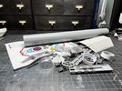
With that straightened out I started on the wing extensions and figuring out the measurements. I've read of people doing their wing extensions in varying widths:

12.6mm
15mm
15.8mm

I know there are some templates out there and I'm capable of making my own but I found it faster to cut some strips out of card stock and just taping on the wings to see what looks best. Afterwards I would then just trace the pieces onto another piece of card to make the final template. I know it seems like a lot of work it's just a quicker way of working for me.

IMG_4932.jpg


IMG_4933.jpg


IMG_4934.jpg


I started with the 15mm measurement and it didn't quite look right so I tried 1/2". Again, not looking right. Too small.


IMG_5051.jpg


In the end I found myself in that familiar place we've all been in where I was getting tired and nothing looked right.

IMG_5052.jpg


I'd be curious to hear from anyone out there what measurements for the wings you used.
 

Attachments

  • E61A622C-6043-403B-A890-64CC0D06329A.jpg
    E61A622C-6043-403B-A890-64CC0D06329A.jpg
    324.5 KB · Views: 59
Last edited:

I would calculate the extra wing width from here. Picture 022

But without knowing the dimensions of the model wings, I cant help you
 

I would calculate the extra wing width from here. Picture 022

But without knowing the dimensions of the model wings, I cant help you

I've been using those shots as reference as well as the "Chronicles" books.
 
February 18, 2024

What a difference a nap makes! I came back with a clear head and a clear realization of where I was screwing up. In my head I was thinking 15mm extensions but in reality I was measuring 15mm from the edge of the wing and adding 5mm to it to glue on the backside. *facepalm*

With that straightened out I remade my template and transferred it to the .75mm styrene and cut it out.

IMG_5063.jpg


There's a piece on the wing that encroaches on the extension. That's easily remedied with a chisel blade.

IMG_5061.jpg


Measurements were taken from RPF member Moska's amazing parts map to accommodate the Leopold greeblies and transferred to the pieces.

IMG_5068.jpg


The notches were cut a little smaller and I "snuck up" on the fit using a small file and the part as a guide.

IMG_5069.jpg


At this point I got into the groove and forgot to take photos of some key moments like scribing, and gluing the pieces in place. The good news is I have another one to do so I'll get some pick up shots.

Overall I'm pleased with the results and think I had a good recovery from yesterday.

IMG_5072.jpg


IMG_5075.jpg
 
Last edited:
iirc at front and rear the trim should double what is visible outside of the diffuser pattern or 'just' to the inside of it, then project up the correct angles from there. That may mean 7 and 7 F/R and 7 and 8 T/B, which would mean yeah, a 15mm extension starting from the edges of the wing source would be in the ballpark. Use the 10/4 to help. And you're correct on the wing re-use, two kits. Last- don't be too eager to eliminate all of the flash. Some has to be, but some small bits are on the bomber-- every TIE molded with them and they aren't all ground down. Check your ref carefully.
 
iirc at front and rear the trim should double what is visible outside of the diffuser pattern or 'just' to the inside of it, then project up the correct angles from there. That may mean 7 and 7 F/R and 7 and 8 T/B, which would mean yeah, a 15mm extension starting from the edges of the wing source would be in the ballpark. Use the 10/4 to help.
Thank you. I have no idea what any of that means. Let’s start with the numbers 7 & 8. What are you referring to? 10/4?
 
Hehhh just that your extensions are likely to be about add 7mm front and rear, 8 top and bottom. And to use the kits parts that detail things to help you be certain of those numbers by making some proportion measurements and such, tack them in place with some pvc and see how they look. I got a dozen vintage ship kits in a few days ago, so will revisit this myself before long. Huge project right now, but hopefully this Summer.
 
Hehhh just that your extensions are likely to be about add 7mm front and rear, 8 top and bottom. And to use the kits parts that detail things to help you be certain of those numbers by making some proportion measurements and such, tack them in place with some pvc and see how they look. I got a dozen vintage ship kits in a few days ago, so will revisit this myself before long. Huge project right now, but hopefully this Summer.
Ok, I get it. Yes! We’re on the same page. I’m a big fan of mocking things up first hence the card stock and masking tape on everything.
 
Glad to see this thread started after seeing your tease elsewhere. Nowhere near the top of my "next build" list but looking forward to the details to learn for future reference.
 
February 25, 2024

Scribing is not something I have a lot of experience with but I won't be able to say that when all this is finished.

IMG_5097.jpg


When I did the other wing I transferred the measurement for the scribed line that runs around the perimeter of the inside of the wing with a pencil and compass.

IMG_5098.jpg


On the first wing I did I scribed the line with a carbide tip scriber, using Dymo label tape as a guide and the results were okay at best. I'm by no means a perfectionist with everything but they just didn't look right. They didn't have much of a diameter to them. I tried experimenting using a fine scribe/chisel on some scrap and it dug into the styrene with no real control.

IMG_5103.jpg


The MVP ended up being my old Tamiya scribing tool buried in the drawer. It created the perfect width while removing the right amount of material with a couple of passes.

IMG_5101.jpg


IMG_5104.jpg


That inspired me to go back and carefully redo the first wing. By no means are they perfect but it's at my acceptable "camera grade" level of quality. I filled any unsightly gaps and/or scratches with Bondo or CA. A quick primer, touch up and sanding later and with both wing extensions completed, I treated myself by gluing on the first of the greeblies.

IMG_5118.jpg


Next subassembly to work on was the cockpit dome. I invested in a surface gauge for marking and scribing because it seemed like it would be helpful on this build. I was right.

I took a measurement of the windscreen and did my best to transfer the measurement to the 2" acrylic dome.

IMG_5108.jpg


Using that point as reference I used the surface gauge to scribe a line around the circumference of the dome.

IMG_5109.jpg


Enter what I have dubbed the "Poor Man's Lathe". I saw this technique used on Guy Cowen's build and it seemed like the simplest way to cut the dome. It's a Dremel cut off wheel chucked in my drill press with the table raised to the wheel. The drill press is turned on and you CAREFULLY turn the dome against the wheel, slowly cutting in a little at a time. I would also recommend setting your drill press at it's lowest speed so as not to melt the acrylic.

IMG_5110.jpg


IMG_5111.jpg


It worked perfectly! Unfortunately my measurements weren't perfect...

IMG_5112.jpg


I cut off too much but fortunately I bought two domes just in case. I based the new measurement off the old dome, scribed the new one and repeated the process. After sneaking up on the fit with some sanding I had a perfect fit!

IMG_5115.jpg


I've started practicing scribing the lines that will go on the dome and have quickly realized that it would be easier with an ABS dome rather than an acrylic one so I will bet ordering a new pair.

Here's a question to those that have built a TIE bomber: What dimensions did you use for the ribs that go around the two fuselages? I have been trying to use photos and schematics and I would like to know if I'm even close.

13415398_1109759279089083_2758333812704441166_o.jpg


I have the fuselage (pipe only) length at 3.5". I find this suspect as everywhere I've read it's 4".
11 x "ribs" at 1/16" width each.
12 x grooves in-between the ribs .6mm wide.
That would make the width of the whole section to be 15/16"

My gut is telling me none of this is right.
 
Last edited:

Your message may be considered spam for the following reasons:

If you wish to reply despite these issues, check the box below before replying.
Be aware that malicious compliance may result in more severe penalties.
Back
Top