Revell Imperial-II Star Destroyer - second attempt 5 years in the making

giuliodondi

New Member
In 2019 I built the Zvezda 1:2700 ISD kit, my first kit built since my teenage years. That kit would be my first try at fiber optics lighting.
It was supposed to be a one-off endeavour to make a nice home showpiece, so no build log as well as corners cut left and right (impatient me).

This thread is about the second attempt, with a lot more attention to detail. So I'd like to start the build log by showing the previous attempt and list all the things I was going to improve on.

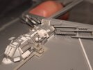
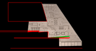
- Since the ISD is meant to be a grey triangle, I thought I could get away with coating everything with grey primer and calling it a day. No panelling, highlighting of details, weathering etc..
- I used a primer not meant for modelling and I put way too many coats to try to make everything uniform. Lots of detail lost in the process
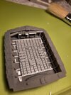
- No kitbashing or detailing whatsoever, except a very sorry afterthought attempt in the rear trench recess
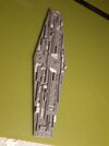
- Used 0.75mm fiber optics, too big for this scale, and in a few places they're not placed uniformly
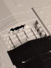
- trench and hangar bay LEDs are too bright
- An accident on one of the superstructure roofs badly re-touched, more lost detail
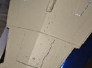
- The seam between the two hull sections was filled with thick acrylic paint and painted over, as opposed to putty and masked with greeblies. Looks poor and it also catches dust more than the surroundings
- The display can use some improvement. I like the underside mirror thing, but the triple stilts look janky


20190529_115001.jpg


20250713_165637.jpg
20250713_165724.jpg

20250713_165803.jpg

20250713_165740.jpg
20250713_165752.jpg
20250713_165841.jpg
20250713_165909.jpg
20250713_165946.jpg
20250713_165824.jpg

20250713_170059.jpg


The second build began in October 2020 as a Covid lockdown project. Now, in July 2025, it's coming along nicely but nowhere near finished. In the following posts I'll showcase all the pictures I collected in the meantime
20250713_164911.jpg
 

Attachments

  • 20250713_165909.jpg
    20250713_165909.jpg
    3 MB · Views: 14
The first build was pretty impressive for a first effort since being a kid, especially with the lighting and the base

Looking forward to the second build. I think faint panel lines and odd colored panels would be an improvement over to the first build

Like on the ESB filming model you can see the subtle tone variations. A very fine point mechanical pencil would be a good way to add/darken the existing panel lines. Plus if you make a mistake, you can literally erase it. Just be careful with weathering and stay away from heavy/ drak washes or heavy handed weathering. A little misting here and there with the lighter color than the base color to fade stuff would be more appropriate

1752500824960.png

1752501154565.png
 
2020-2021: First attempt at greebling

These are my first experiments with styrene stocks and harvesting parts from other kits. At first I even tried recycling old thick optic fibre that I wasn't going to use, as well as the part sprues themselves.
I started off from the engine section:
20201018_201742.jpg
20201018_201803.jpg
20201018_201811.jpg
20201018_204707.jpg

20201018_204605.jpg

Several of these details will be amended much later down the line. I decided to go for thick pipeson the large engine bells.
The white kit parts as well as the brass railings are from a very old Titanic kit I never ended up building.

Then I invested in flat styrene strips and 0.3mm HSS micro-drill bits.
These are the olny ones that don't snap after 2 holes drilled, but they require low speed and care not to gunk up the bit with melted plastic.
Time for the bridge faceplate (This will receive more detailing years on):

20201121_234740.jpg

First holes drilled in the top hull islands, with qa couple accidents here and there:
20201121_234941.jpg
20201121_234959.jpg


It's in the middle of this that I invested in the Falcon3D parts set.
The hangar receives further details as well as the 'roofing' harvested from the original Revell hangar:
20211122_014817.jpg

The hangar section of the lower hull is excavated and flattened, no hull details yet:
20211230_194906.jpg
20211230_194923.jpg


The tower spine also gets the waste chute part, still open at the far end as I hadn't worked out the LEDs yet:
20211124_002747.jpg


And finally the elongated pier at the front of the superstructure (This will also receive more work):

20211125_230308.jpg
20211125_230321.jpg
 

Attachments

  • 20211122_002402.jpg
    20211122_002402.jpg
    1.2 MB · Views: 12
  • 20201121_234755.jpg
    20201121_234755.jpg
    1.1 MB · Views: 13
Last edited:
2021-2022: more kits for kitbashing:

At this point I was getting bored of the Titanic parts and I researched which kits I could cannibalise for greeblies. I selected a Trumpeter 1:700 Tirpiz.

Little details on the forecastle (also not yet finished):
20220105_234251.jpg
20220105_234302.jpg

The bridge roof is prepared for the Falcon3D sphere arrays and detailed:
20211228_001123.jpg
20211228_121354.jpg
20211228_121452.jpg


The two the superstructure roof pieces:
20211228_001023.jpg
20220105_235342.jpg

20220107_210122.jpg
20220107_210055.jpg


The process of drilling the fiber holes into the superstructure walls, then marking them onto the scaffolding with a hand drill:
20220106_151213.jpg
20220106_151457.jpg
20220106_151722.jpg


and finally drilled through with a coarser tip:
20220130_120731.jpg


Then, long summer days workign on all the superstructure parts:

20220821_173644.jpg
20220821_173652.jpg
20220827_193650.jpg
20220827_204805.jpg
20220829_155430.jpg


and some group pictures:
20220831_204148.jpg
20220831_204156.jpg
20220831_204211.jpg
20220831_204220.jpg
20220831_214055.jpg
20220831_214101.jpg
20220831_214114.jpg
 
Last edited:
YES! Greebling! I had missed the arduous task done with my Zvezda/Revell (which I have still not finished) - and a few months ago I found myself looking at the Revell Build-And-Play Rogue One ISD TOY that they released as a model kit, and .. I was impelled to suddenly rip out all the toy electronics and accurize it better. I originally wanted to just fix the side trench height and add detail - and.... well, I got myself suckered into doing the whole thing.

This was more difficult than the 1/2700 because the scale for this is closer to something like 1/4100 so the greeblies that I had to hand carve was tiny and miniscule compared to the 1/2700. I'm not lighting this kit, I just wanted to accurize and paint it.

Original Revell kit.jpgrear port engines2.jpgrear port engines.jpgPort Cake.jpgSB trench3.jpgSB Top.jpgSB trench2.jpgSB side2.jpgSB trench1.jpgSB side1.jpg

I am glad to see you tackle the bigger kit and share your progress. You are making it look good.
 
The first build was pretty impressive for a first effort since being a kid, especially with the lighting and the base

Looking forward to the second build. I think faint panel lines and odd colored panels would be an improvement over to the first build

Like on the ESB filming model you can see the subtle tone variations. A very fine point mechanical pencil would be a good way to add/darken the existing panel lines. Plus if you make a mistake, you can literally erase it. Just be careful with weathering and stay away from heavy/ drak washes or heavy handed weathering. A little misting here and there with the lighter color than the base color to fade stuff would be more appropriate

View attachment 1948945
View attachment 1948947

Thanks for the tips! when the time comes for painting will definitely research on panelling techniques and other builds. Far, far down the line from the current status, though
 
YES! Greebling! I had missed the arduous task done with my Zvezda/Revell (which I have still not finished) - and a few months ago I found myself looking at the Revell Build-And-Play Rogue One ISD TOY that they released as a model kit, and .. I was impelled to suddenly rip out all the toy electronics and accurize it better. I originally wanted to just fix the side trench height and add detail - and.... well, I got myself suckered into doing the whole thing.

This was more difficult than the 1/2700 because the scale for this is closer to something like 1/4100 so the greeblies that I had to hand carve was tiny and miniscule compared to the 1/2700. I'm not lighting this kit, I just wanted to accurize and paint it.

View attachment 1949268View attachment 1949269View attachment 1949270View attachment 1949271View attachment 1949272View attachment 1949273View attachment 1949274View attachment 1949275View attachment 1949276View attachment 1949277

I am glad to see you tackle the bigger kit and share your progress. You are making it look good.
Thanks!
Actually your 1/2700 build has served as an inspiration for my own, especially with raising the trench which will come in not too long.

That's some seriously fine work at that small scale!
 
2022-2024: more hull details, then work wind-down

I kept working on this the whole summer of 22, then more an more sporadically as my actual employment work was keeping me in another city.

Modifications to the superstructure forward tip:
20220831_235301.jpg
20220901_001255.jpg
20220831_235911.jpg


Roofing details on the pentagon structure (will receive more):
20220901_125145.jpg
20220901_125402.jpg


Photo-etch details around the turbo-lasers:
20220901_164238.jpg
20220903_142729.jpg


More superstructure and top hull details:
20220903_142720.jpg
20220903_142738.jpg
20220903_142752.jpg
20240610_234830.jpg
20240610_234837.jpg
 

Attachments

  • 20220901_001305.jpg
    20220901_001305.jpg
    1.8 MB · Views: 13
Last edited:
2025: superstructure work resumes


This spring I found the motivation to resume work, and setup a small work-bench space in my flat.

I glued the top floor superstructure parts together save for the large roof piece, might need to keep it open for wiring:
20250524_130509.jpg

I put a couple greeblies that 'clib a step' there at the front:
20250524_152341.jpg
20250530_014137.jpg


I also put details on the underside of the back ledge of the roof part:

20250527_002851.jpg
20250527_003057.jpg
20250527_003113.jpg

20250530_014157.jpg


And on the ledge of the middle roof part as well:
20250604_013553.jpg


I should mention the additional greeble sources I acquired:
9 Tamiya Japanese ship kits I got for cheap:
20240610_221623.jpg


As well as parts from two old half-broken kits I made when I was 12 or something, 1:2700 Venator kit and (i think) 1:400 Titanic, both by Revell.
This is before paint-stripping with oven cleaner:
20240512_153211.jpg
 
Last edited:
2025: revenge of the pipings

First, re-worked that empty spot above the central viewing platform (striggling to invent names for all the sections):
20250526_225954.jpg


Then, I miiight have gone mad with the pipework at this stage:
20250605_000757.jpg
20250605_000811.jpg
20250613_014933.jpg
20250613_014915.jpg
20250617_023147.jpg
20250617_023158.jpg
20250617_023208.jpg
20250617_023224.jpg


One shot in the dark was to add turret barbettes at the very stern of the ship. They will receive two of the Venator dual turbolaser turrets.
In my lore, this was an afterthought modification to this ISD-II after someone pointed out the weak spot at the back of the ship:
20250611_023408.jpg


And, the superstructure as a whole:
20250617_023339.jpg


I'm calling the superstructure mostly done, barring the occasional greeble to cover a seam.
The hull will most likely receive scattered details once it's time to join the front and back segments
 
Last edited:
2025: Bridge detailing, part 1

More detailing on the bridge front faceplate, including replacing two brass details with styrene strips, as they were flimsy and rattled themselves off:
20250624_213757.jpg
20250629_165524.jpg


Realised I never showed the antenna cross-bracing (work was done years ago):
20211228_001038.jpg


a ton more detailing on the bridge roof (looking at the pictures I realise there's a detailing not quite set right that I'll need to fix):
20250624_014048.jpg
20250624_014059.jpg

and with all the array parts:
20250624_083532.jpg
20250624_083512.jpg
20250624_083402.jpg

the two sides:
20250624_215121.jpg
20250620_011743.jpg

And the back. This is not finished as is, I intended to add more detail when the tower neck will be sorted out:
20250629_133608.jpg
 
Last edited:
2025: Bridge detailing, part 2

I'm particularly pleased with the underside work. Taking inspiration for other builds, I too recreated the ESB equipment pits:

Excavation starts with a drill bore and then hand-chiselled to a square:
20250624_231036.jpg


20250624_233709.jpg
20250625_011916.jpg

the pits were built larger on purpose, then detailed wall by wall:
20250627_002212.jpg
20250627_004844.jpg

I did my first LED tests at this stage. Full-brightness 5v LEDS are too bright and will cast a light on the superstucture roof. On the latter two images I tried undervolting them to 3.3V
20250627_175628.jpg
20250627_183731.jpg
20250627_184142.jpg

completed work:
20250627_194626.jpg

20250627_194643.jpg
20250627_194653.jpg

Finally, the back, sides and underside of the bridge are glued together:
20250629_134202.jpg
20250629_144117.jpg
20250629_144915.jpg
 
Last edited:
2025: Tower neck, part 1

The infamous bridge tilt, one of those subtle details which you can't unsee once you're aware of it.
Didn't take long for me to decide I had to do something about it, or every time I would look at the finished model I would be reminded of it.

The issue is that the bridge and the roof of the neck come out of the box parallel to the ship centreline (the waist trench). While in the original ESB studio model, they need to run parallel to the superstructure roofs, which follow the slant of the upper hull:

neck_0.png


I saw 2 possible solutions:
neck_tilt_2.png
neck_tilt_1.png


Solution 1 is the one most builds seem to go for. Tilt the entire neck-bridge assembly forwards, cut out the bottom edges and excavate a new slot for the superstructure overhang. Solution 2 is actually what came most natural to me. Leave the neck mostly as is and pivot the bridge forward at the attachment.

  • solution 1 leaves the neck details parallel to boththe bridge and the superstructure as they should.
  • solution 2 is far easier to craft. No precise chiselling that must be exact on both sides, and the extra wedges can be re-made if they're not right
  • solution 2 would have neck details that are not parallel to either the superstructure or the bridge, but by a minor angle
  • likewise with solution 2 there's a break angle between the bridge and the roof of the neck
  • solution 2 creates a sharper angle between the front of the neck and the 'chin' of the bridge, which to me looks closer to the ESB model
  • in solution 1, those square details at the base of the neck would look very tall
I didn't feel confident enough making solution 1 look right, so I went for solution 2:
20250629_154526.jpg
20250629_153555.jpg

20250629_154913.jpg
20250629_153635.jpg


and a few shots of the resulting:
20250629_164012.jpg
20250629_164106.jpg
20250629_164232.jpg
20250629_165048.jpg


around this time I also took care of the far wall of the trash chute, with a passage for a future LED:
20250629_021003.jpg
20250629_015341.jpg


I used one of the hangar gate parts harvested from the old Venator kit.
Finally, the front neck part:
20250624_210004.jpg
 

Attachments

  • neck_tilt_2.png
    neck_tilt_2.png
    1.2 MB · Views: 7
Last edited:
2025: Tower neck, part 2

The neck parts receive a fair dose of greeblies, especially to mask the wedges I added:
20250629_181036.jpg
20250630_233817.jpg


those little flaps are meant to integrate with further details on the backside of the bridge:
20250703_023558.jpg


I used some sawtooth styrene sheeting to craft those plate parts at the base of the neck:
20250701_010004.jpg
20250701_024324.jpg


The completed neck is assembled for fit tests:
20250703_023714.jpg
20250703_023641.jpg


Note the piping at the top of the neck, slanted forward slightly to try and dampen that break angle effect.
20250717_225550.jpg
20250717_225618.jpg
20250717_225636.jpg
20250717_225716.jpg


Not perfect by any stretch, and there will be more filling in at the very bottom of the neck spine.
But still rather pleased with the result, and it's quite something to see the thing start to take the shape it should have
 
2025: Tower neck, part 1

The infamous bridge tilt, one of those subtle details which you can't unsee once you're aware of it.
Didn't take long for me to decide I had to do something about it, or every time I would look at the finished model I would be reminded of it.

The issue is that the bridge and the roof of the neck come out of the box parallel to the ship centreline (the waist trench). While in the original ESB studio model, they need to run parallel to the superstructure roofs, which follow the slant of the upper hull:

View attachment 1950152


I saw 2 possible solutions:
View attachment 1950156View attachment 1950150

Solution 1 is the one most builds seem to go for. Tilt the entire neck-bridge assembly forwards, cut out the bottom edges and excavate a new slot for the superstructure overhang. Solution 2 is actually what came most natural to me. Leave the neck mostly as is and pivot the bridge forward at the attachment.

  • solution 1 leaves the neck details parallel to boththe bridge and the superstructure as they should.
  • solution 2 is far easier to craft. No precise chiselling that must be exact on both sides, and the extra wedges can be re-made if they're not right
  • solution 2 would have neck details that are not parallel to either the superstructure or the bridge, but by a minor angle
  • likewise with solution 2 there's a break angle between the bridge and the roof of the neck
  • solution 2 creates a sharper angle between the front of the neck and the 'chin' of the bridge, which to me looks closer to the ESB model
  • in solution 1, those square details at the base of the neck would look very tall
I didn't feel confident enough making solution 1 look right, so I went for solution 2:
View attachment 1950165View attachment 1950164
View attachment 1950167View attachment 1950166

and a few shots of the resulting:
View attachment 1950168View attachment 1950169View attachment 1950170View attachment 1950171


around this time I also took care of the far wall of the trash chute, with a passage for a future LED:
View attachment 1950173View attachment 1950174

I used one of the hangar gate parts harvested from the old Venator kit.
Finally, the front neck part:
View attachment 1950183
You are a wiser man than I am. I tried a haphazard take on version 1 and messed up the neck pieces on mine.

I was finally able to buy replacements of the bay of e.
 
Casting greeblies, and hangar work

The first post that reports new work and not retrospective.

I will soon begin work on raigin the waist trench by (probably) 2mm. Taking inspiration from Moska's work, I made resin casts of the trench parts so I could use them for the coarse detailing on the extra height.
This is my first time working with resin and one-part moulds in general, so the result won't be stellar. I made a mouldingbox with foamboard and play-dough, then used 2-part silicone:
20250707_194701 (1).jpg
20250711_003422.jpg


No pictures of the polyurethane resin casting as I was more concerned with not spilling or breathing toxic components. Only the result:
20250717_225158.jpg


This is 3 casts, two from one mould and one from the other. There is a fair amount of bubbles here and there but I think I can work around them and greeble them up. Else, I still have the moulds and plenty of compound to try again if need be.

I'm waiting for the styrene strips of the correct dimensions, so in the meantime I set to work on the hangar bays:
20250720_033109.jpg
20250720_033051.jpg

20250720_220554.jpg
20250720_025812.jpg

I re-did the greebling on the two open hangar bays as they were hiding the hangar roof details. Also greebled up the aft end of the main ventral bay, as it was rather barren.

I also set to work on excavating another hangar on the forward bay. Greeblies both on the forward side and the aft:
20250720_163233.jpg
20250720_171559.jpg

20250720_202816.jpg
20250720_222445.jpg

20250720_234307.jpg


Drilling and chiselling the one hangar bay was fiddly enough that I didn't do it again for the aft side.
Finally, took out the 0.3mm hss bits again for fiber optic drilling on the forward hull islands:
20250721_004357.jpg
20250721_004410.jpg
 

Attachments

  • 20250720_161116.jpg
    20250720_161116.jpg
    760.9 KB · Views: 0
Back
Top