"Reddish Jammer" Y-Wing Build

To build the nacelle tie-down subassembly:
upload_2019-1-15_19-24-11.jpeg

Start with these four pieces, and then modify as follows.

upload_2019-1-15_19-23-46.jpeg


upload_2019-1-15_19-24-47.jpeg

Then glue that little sucker, or half of it, with the raised ridge on the inside, into the bottom of the Kettenkrad pieces, like so:
upload_2019-1-15_19-25-28.jpeg


Start here with your Kettenkrad tie-down greeblie, and sand/plane it until its practically one-plane surface at top/rear section...
upload_2019-1-15_15-52-6.jpeg


upload_2019-1-15_15-52-6.jpeg


Then do the following, repeating but modifying the steps shown earlier on how to perfect your 3-piece nacelle-tie-down clip subassembly.

upload_2019-1-15_15-54-54.jpeg

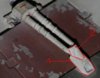
Cut the Bandai 1/24 wheel struts roughly as follows, NOT cutting the bottom edge flush with the strut piece, in order to accommodate the angle of the "mount" on the pantyhose nacelle.

upload_2019-1-15_19-19-49.jpeg


upload_2019-1-15_15-56-29.jpeg

Note the angle, leaning inward on top, outward on bottom...

upload_2019-1-15_15-57-14.jpeg

The basic idea is to angle these out at bottom as much will be allowed and angle them together at the top as much as possible, and THEN make the top cross-cut to create the upper plane of the nurnie on top of which you'll glue the two little "nubs" of the cut-offs from the center of the wheel piece.

upload_2019-1-15_19-21-55.jpeg

You're cutting off a ridiculously small tip-top piece from here, on both struts, and saving those tiny pieces to glue on top.

upload_2019-1-15_15-57-14.jpeg


You're angling them together at top to produce this effect:
upload_2019-1-15_19-12-57.jpeg


For this result, once it's all put together and you like the angle:
upload_2019-1-15_19-13-59.jpeg

Here's a close-up
upload_2019-1-15_19-29-22.jpeg


And here's a comparison shot with the previous version I made:
upload_2019-1-15_19-30-43.jpeg

On this, you can see that the one on the left (earlier version) has "flat walls" while on the right (corrected version), has the "angled version" that DaveG pointed out is on the original. If you "work it" even more, which I may yet still do, you can get an even more severe angle from top to bottom, and you can get a better flat plane surface on the Kettenkrad piece, which is something I only discovered after it was too late on this one.

So while this newer, corrected version still isn't a "completely perfect" replica of the nacelle tie-downs, it's edging towards pretty dang close, and more importantly, it manifests the key characteristics of the original subassembly without using a fourth "mystery greeblie," which I believe actually solves the mystery, which is that there is no fourth missing/mystery greeblie - there is just a very specific construction technique you must follow. I may be wrong, but as of this date, I really do think this is how ILM did it, technique-wise, when first mastering these. There are some other versions on the Millennium Falcon where the whole "mystery greeblie" section seems very thin and "single-surface", which I would argue is the result of simply taking this structure and thinning it down with a rotary tool on both sides.

I would love your comments, critiques, eagle-eyes, and nitpicks. I'd like to actually "nail this" so feel free to be liberal with your constructive criticism. If you need further shots, or measurements, or whatever, let me know.
 

Attachments

  • upload_2019-1-15_15-54-54.jpeg
    upload_2019-1-15_15-54-54.jpeg
    142.3 KB · Views: 245
  • upload_2019-1-15_15-54-54.jpeg
    upload_2019-1-15_15-54-54.jpeg
    169.8 KB · Views: 243
  • upload_2019-1-15_15-54-54.jpeg
    upload_2019-1-15_15-54-54.jpeg
    137.3 KB · Views: 246
  • upload_2019-1-15_15-54-54.jpeg
    upload_2019-1-15_15-54-54.jpeg
    155.8 KB · Views: 243
  • upload_2019-1-15_15-54-54.jpeg
    upload_2019-1-15_15-54-54.jpeg
    137.3 KB · Views: 236
  • upload_2019-1-15_19-23-29.jpeg
    upload_2019-1-15_19-23-29.jpeg
    106.7 KB · Views: 241
Yeah, but how do you transport that sucker without all the micro-greeblies always breaking or falling off?

upload_2019-1-27_8-14-24.jpeg

The Pelican 1615 Y-Wing, er, Air Case, with Interior Dimensions that are PERFECT for this bird: 29.59" × 15.50" × 9.38"
This one is with "Pick-n-Pluck" foam, but I would also recommend their "Kaizen" foam if you want to create a truly custom fit.

Has enough room at the front to make mini-compartments for the canopy, guns, etc. if you like.

When you design it, make SURE to face it "head down", so the canopy/forward fuselage is aimed towards the end with wheels; this way all the weight, if any shifting does occur, hits the L'eggs Pantyhose Container Nacelle structures, and neither your front guns nor your rear vectral "super-delicate" greeblies will get any undue pressure. Have rolled it into the city, onto and off airplanes where it went through baggage claim, and so far no breakage has ever occurred.

Photo of unfinished Y-Wing in case for illustration purposes only; Y-Wing NOT included in Pelican 1615 Air Case purchase; Use only with professional supervision; Tax, tag, and title extra; Your results may vary; Past performance does not guarantee future results; Void where prohibited; Some restrictions apply; At participating dealers only; Please drink responsibly; Member FDIC; Ask your doctor today; While supplies last; This message paid for and approved by Citizens for Safer Y-Wing Storage and Transportation.
 
I did something like that awhile back to ship mine to the painter.
I used a hard sided archery case and made a fitted foam cradle.
My cradle design put pressure on the tail section, and it wound up warping the resin. I have since replaced the tail section with 3D printed parts.

Yours looks more secure than mine did. Great job.
 
To make the dampers, or nacelle clip tie-downs, or whatever their official nurnie-greeblie-thingie name is, I think I may have serendipitously (after three different attempts) figured out the mystery of the "missing piece": there is no missing piece.

The builder (who I think was Dave Beasley) of this subassembly simply "recycled" all available material, which were exactly these three parts:
View attachment 943562
From left, clockwise: 1.) Bandai 1/24 Messerschmitt Bf-109E4 Parts #B17 and B18 (5-step landing gear struts, ONLY the Bandai kit will provide this). 2.) Tamiya 1/35 Panzer Kampfwagen III Ausf. M/N (Kit No.35011), Part #C8 (Gun Barrel mount, and NOT part # A54 which looks very similar but is slightly different on top). 3.) 1/9 Kettenkrad manufactured originally by ESCI in 1975, and later re-issued variously by Ertl, Revell, Hasegawa, Dragon, or now Italeri, part #226P (or its identical twin #226Q). The trick is in a.) how you modify them (esp Parts 1 and 3), and b.) how you DON'T THROW AWAY YOUR CUT-OFFS, SCRAPS, or "extra sprue" lying around after modifications...

View attachment 943595
See those TWO little nibs that are cut off the landing gear struts on the wheel part? KEEP THOSE -- they become the "rivets" that later show up on top of the greeblie.

Now notice something else...
View attachment 943597
See how the landing gear top hinge section, that would go into the airplane (and allow the strut to swing in/out of the landing gear recess bay) is, when cut off, EXACTLY the width of the bottom inset of the Kettenkrad tow hook (Lower Right section of this picture)? That's not a coincidence either.

View attachment 943598
So you should end up with something like this, before you begin any major surgery on the landing gear struts' circular sections.

View attachment 943599
Then you should cut off the outside edge, on both sides, of the strut, using the natural angle of your clippers to where they "hit" the base but go back far enough to remove the "obvious" perception that this is a landing gear strut, and sorry for the crappy picture that is out of focus, but that's the only one that was remotely post-able. After this, you're going to sand it down using the SMALLER of the two sanding wheel options that come standard in your Dremel tool.

So that the end result...
View attachment 943600
looks something like this. What you're trying to do is "narrow the inserted section" enough so that it fits "perfectly" in between the opening of the Kettenkrad hook's negative space, so this is the trickiest part and so far I've never done it perfectly, even though I'm getting closer.

View attachment 943601
So before final modifications, it looks like this, but of course you have to build this on a dummied-up engine and nacelle core (L'eggs Pantyhose container, modified down) so that you're getting all the compound angles as close to perfect as possible. And then, the most delicate cut of all, which I have marked with a Gundam pen first...
View attachment 943604
That line/angle is crucial, because it is what creates the perception/illusion of a third/missing nurnie in this whole subassembly.

View attachment 943605
This is what it looks like "before" the correction for the nacelle nosecone angle, and the cut, and the final terrifying commitment of the sprue cutter...

View attachment 943607
And here is the rough-up, before gluing and final back section cut. See how it begins to look like the original subassembly?

Then you glue those little buggers on that you didn't throw away earlier, after cutting them way down to just tiny nibs/rivets, meaning you are just using the very tip-top of the leftover piece.
View attachment 943609
Looking familiar? We're getting there...

Meanwhile, on the UNDERSIDE, what you've done is cut off HALF of the landing gear top section, creating this:
View attachment 943610

And then, you cut off the very back top circular section, making it flush with the rest of the piece, and all of a sudden...
View attachment 943611
Viola! You have a musical nurnie that looks remarkably like the original...

View attachment 943543
Or at least, close enough for government work (make final clean-ups, adjustments, and whatnot with Perfect Plastic Putty or your preferred filler of choice.
View attachment 943564
Here's the original, for comparison's sake.

Has this solved the mystery of this missing mystery greeblie? I'd love to hear your thoughts, but I think it does, and I am mostly of this opinion because a.) hundreds of dollars of train bridges, cranes, track barriers, truck trusses, still girder bridges, and other steel-girder construction model kits later I still haven't found anything close, b.) this method explains both the 1.) strange spacing and 2.) different sizes/heights of the two top bump "rivets" on this particular nurnie, and c.) modeling putty of this type ALSO explains the indent in what would be a "puttied-in" section of the nurnie, since the putty of the 1970's putty was famous for drying out and "sucking in" as it dried, leaving little impressions or concavities like that found on the far left picture above.

Mad props and thanks go (again) to Dave Goldberg for his 3D printed version of the nurnie, which he modeled and which I used as a reference/template for making some of these guesses.

View attachment 943563

View attachment 943596
Very Well done, I spent some time looking over any kit with large Rivots, but none were anywhere near that size, and when they were not in that dual setup on that angled piece. It makes sense that he would spend time creating this once or twice as he knew he was going to be casting it
I've always looked at the Millennium Falcon damper struts as these were the same assemblies, and yours is much closer than anyone else's I have seen, it feels right if you know what I mean.
if you look at Falcon strut the first image you can see a separate triangular shape in the upright, that could be a skim of filler or an optical illusion caused by a hollow, not unlike your half modified example.
Again well done
 

Attachments

  • falcon  struts 3.jpg
    falcon struts 3.jpg
    284.5 KB · Views: 369
  • falcon  struts 2.jpg
    falcon struts 2.jpg
    301.5 KB · Views: 366
  • falcon  struts 4.jpg
    falcon struts 4.jpg
    324.1 KB · Views: 352
  • falcon struts.jpg
    falcon struts.jpg
    110.6 KB · Views: 343
Where is that center inner ring from? Was it kit-bashed? Or machine-tooled?
View attachment 961124

I believe it was kit-bashed. I believe this for a couple of reasons:
1. Because whenever ILM could find the shape and size they were looking for in a model kit, it saved them time and money on machine-tooling.
2. Because on the actual model (unlike the DaveG perfectly-fitting 3D prints shown above), the center ring is slightly "off" of being perfectly flush with the inside of the Sealab Crane Part #59 double-sided/mirrored nurnie, as seen in the detail picture below of the Alan Ladd rear vectral
View attachment 961126

3. Because I believe I have found the part.

4. And because this part is perfectly "mismatched" to the Sealab nurnie in the same way the original was.

Here is the part on top of DaveG's 3D file printed equivalent:
View attachment 961101

Here is DaveG's 3D-file printed ring piece on top of the kit bashed part
View attachment 961102

Here are the two parts side by side.
View attachment 961103

Here is the part fitting "perfectly" inside DaveG's 3D vertical rear vectral fin, overhead view.
View attachment 961098

Here is the part fitting "perfectly" inside DaveG's 3D vertical rear vectral fin, side view.
View attachment 961100

Here are the measurements of the part, roughly 38mm inner diameter and 40mm outer diameter, but not "exactly" these numbers:
View attachment 961104
Inner diameter 38.62 (but don't take this as gospel, as I'm measuring a flexible part and each time I do it I get a different number, so even this is a "pretty close" guesstimation)

Here is the outside diameter:
View attachment 961105
Outer diameter is 40.54 (but again, don't take this number as gospel). The key is that it is pretty much 38mm on the inside and 40mm on the outside, with roughly 1/4 a milimeter (0.25mm) of wiggle room (i.e., the limitations of either my tool or my measuring abilities)

Here it is fitting inside (but just barely) into DaveG's 3D-printed horizontal rear vectral fin:
View attachment 961072
But here is where the part does not fit "perfectly" into DaveG's 3D-printed part, as the vertical ventral fin is slightly too "tight" to accept the kit bashed part, despite fitting perfectly into his other 3D-printed part: the DaveG part is a few mm shy of the full width of two Sealab Part #59's abutted to each other, which can be accommodated for inside the rear ventral ring (modified L'eggs Pantyhose container) by simply cutting off those same number of mms on the outer legs, as shown by the Gundam marketed pieces on the lower assembly in the photo below
View attachment 961106

So here it is sitting at the midpoint inside another version of the horizontal rear vectral fin, with plenty of wiggle room (but perhaps too much by 1-2mm)
View attachment 961107

So now here it is on the center part of a newly created horizontal rear vectral fin (in layout form, not yet glued together), which I believe is closer to the real original nurnie:
View attachment 961073

So where does this mystery greeblie come from?

So glad you asked...
View attachment 961108
The Entex 1/16 the Hon. C.S. Rolls 1908 Rolls Royce Silver Ghost "balloon car" released in 1975.

Sprue G, Part #1 (10 of them per model, or 5 Y-Wings worth) top side:
View attachment 961121

Sprue G, bottom side:
View attachment 961123

Close-up shot, top-side:
View attachment 961122


Top side is "pretty sharp" and "machined" looking on its edges, while the bottom side of the nurnie is softer, more rounded. So there are some discrepancies, as in many photos it looks like it's sharp and machine-edged on both sides.

But it doesn't look so sharp-edged on this archival Y-Wing, however, does it.
View attachment 961125

So the truth is, I'm not 100% certain on this one. But it's an as-yet-undiscovered nurnie, it fits the role, and I'm using it.

You can also get the kit re-issued later by Bandai in the 1980's, and much more common on Ebay.
That looks more like metal wire , brass loop . very consistant curved edge, maybe
 
Vacformedhero: "if you look at Falcon strut the first image you can see a separate triangular shape in the upright, that could be a skim of filler or an optical illusion caused by a hollow, not unlike your half modified example."

Agree that it certainly "looks" like a separate triangular piece, but you can replicate this illusion with sharp-cornered sanding files and the right amount of putty in the recesses.
 
Anyone know these 8 greeblie identities? They are on the bottom fuselage, and I think this picture is from the Neisen master. These greeblies seem to be accurate for the bottom of Gold 3, but I can't tell if they are on the bottom of other/all Y-Wings or not (simply b/c my reference photos don't show this area very well or clearly)
Unknown.jpeg

1.
2.
3.
4.
5.
6.
7.
8
 
Hai idea di cosa sia il n. 4?
[/CITAZIONE]
I don't know where that part comes from ... but I'm looking for it, if I find it I'll tell you.
 
Back
Top