More details on the Vader ROTJ saber - Please archive

Well, I know we don't have all opinions represented here, but I think it's safe enough to assume that the endcap isn't bare metal.

It's either putty, puttied-over metal, painted-over putty, or painted-over metal.

icon_lol.gif


Confusing enough?
 
Ok,
So, I'm starting to get sucked into the added, free hand-cut disc theory. If this is the case, how are we explaining the concave shape?

Yeah David, I think you covered it!! (tall growing fibrous material?
icon_razz.gif
)
Sorry!
 
Well, to resurrect one of the first posts here that somehow got overlooked:

</SPAN><TABLE BORDER=0 ALIGN=CENTER WIDTH=85%><TR><TD CLASS=$row_color>
James Kenobi 1138 wrote:
<HR></TD></TR><TR><TD CLASS=$row_color>
Since the top shell is so beat up and scratched, but the copper underneith the plating is not showing, I have often wondered if they simply didn't just paint the top shell with a silver/buffing paint after ESB to 'spruce-up' the saber a little?

Considering it's condition, I can't imagine they actually had it replated? Too much time and trouble.

I can't see any edge to indicate foil or tape, too clean on the raised button areas.

I'm wondering more and more it it's not just painted silver?


</TD></TR><TR><TD><HR></TD></TR></TABLE><SPAN CLASS=$row_color>

Thoughts on this?
I think it's pretty well within the range of possibility!


FMC: The concave disc thing was addressed by Lonepigeon quite a few posts back. He said that the addition of the Linhof (Kobold) bracket caused it to sink in.
icon_wink.gif
 
My last post on this was totally lost because no one said anything about it, so here it is again.

I was thinking about this all day. I'm sold that there had to be some kind of inner tube. 2 Graflex tubes, a top and a bottom, are not very strong together without the Graflex clamp. With the Graflex clamp, it becomes a pretty solid piece.

On this saber, the midband is just a piece of 1.5 inch tubing cut and wrapped around or a flat piece of metal that was cut and rolled to the midband shape. Even with the strongest glue, I can't see that midband holding the entire Saber together, especially for dueling. Maybe if the midband was screwed to both the top and bottom tubes in several places on the outer circumference, maybe, but not the way the saber is now.

I'm pretty sure that either a metal or PVC tube that was like 11 inches long was inserted inside and glued in place, and then the midband was wrapped around. The inner tube in what made the top and bottom tubes a strong, solid piece.

Now about the endcap. Here is how I would have built the saber. I would have glued the PVC pipe inside the top tube. Then I would have popped the endcap completely off the bottom tube. Then I would have glued the bottom tube to the PVC, making one solid saber. Then I would have stuck the dueling saber blade metal rod through a fender washer and into the saber with the fender washer resting on the inner PVC tube and the metal rod going down the saber handle. Then I would have filled the entire saber with resin or fiberglass or something from the open endcap and wiped the excess flat even with the endcap. Once it dried, I would have wrapped the midband around, attached the control box by drilling and taping the PVC and resin/putty, and drilling and installed the hex-bolts to help keep the inner tube/resin block from moving around or working lose while dueling. I could then add all the other details including the d-ring that I would have either riveted to the resin or glued it to the bottom with the rivets being purely cosmetic.

Okay, let the nit-picking begin.
 
Hmmm...okay James, let's see:


</SPAN><TABLE BORDER=0 ALIGN=CENTER WIDTH=85%><TR><TD CLASS=$row_color>
James Kenobi 1138 wrote:
<HR></TD></TR><TR><TD CLASS=$row_color>
On this saber, the midband is just a piece of 1.5 inch tubing cut and wrapped around or a flat piece of metal that was cut and rolled to the midband shape. Even with the strongest glue, I can't see that midband holding the entire Saber together, especially for dueling. Maybe if the midband was screwed to both the top and bottom tubes in several places on the outer circumference, maybe, but not the way the saber is now.
</TD></TR><TR><TD><HR></TD></TR></TABLE>

Excellent point. Just like the "wood grip theory," it seems HIGHLY unlikely that it could withstand dueling unless it had a solid base - meaning that it went all the way to the bottom!

<TABLE BORDER=0 ALIGN=CENTER WIDTH=85%><TR><TD CLASS=$row_color>Quote:<HR></TD></TR><TR><TD CLASS=$row_color>
I'm pretty sure that either a metal or PVC tube that was like 11 inches long was inserted inside and glued in place, and then the midband was wrapped around. The inner tube in what made the top and bottom tubes a strong, solid piece.
</TD></TR><TR><TD><HR></TD></TR></TABLE>

Gotta disagree with you there, bud...for one, as I've mentioned before, PVC doesn't fit securely within the inner diameter of a Graflex.
Where did you come up with the idea of a metal insert? That's a new one...
icon_smile.gif


<TABLE BORDER=0 ALIGN=CENTER WIDTH=85%><TR><TD CLASS=$row_color>Quote:<HR></TD></TR><TR><TD CLASS=$row_color>
Now about the endcap. Here is how I would have built the saber. I would have glued the PVC pipe inside the top tube. Then I would have popped the endcap completely off the bottom tube. Then I would have glued the bottom tube to the PVC, making one solid saber. Then I would have stuck the dueling saber blade metal rod through a fender washer and into the saber with the fender washer resting on the inner PVC tube and the metal rod going down the saber handle. Then I would have filled the entire saber with resin or fiberglass or something from the open endcap and wiped the excess flat even with the endcap. Once it dried, I would have wrapped the midband around, attached the control box by drilling and taping the PVC and resin/putty, and drilling and installed the hex-bolts to help keep the inner tube/resin block from moving around or working lose while dueling. I could then add all the other details including the d-ring that I would have either riveted to the resin or glued it to the bottom with the rivets being purely cosmetic.
</TD></TR><TR><TD><HR></TD></TR></TABLE><SPAN CLASS=$row_color>

This sounds reasonable...especially your explanation of how the endcap came to be!
icon_wink.gif

Question, though - when you say the "rivets are purely cosmetic," what rivets are you referring to?

Great post, James!
icon_smile.gif
 
I meant that if the endcap was popped out so the saber could be filled with resin from the bottom, but you still wanted the d-ring, you could use sheet metal cutters to remove the d-ring from the endcap and keep the rivets on. The saber was never actually seen on Vaders belt, it could have been glued on or something. I don't know, just throwing out ideas.
 
Well Im not saying there PVC pipe in that saber but there is definitely some kind of tubing in there...It can be seen under the silver button and in the test lamp switch hole...
And I dont think its just bondo either...If bondo were poured in there it would have ran out the holes and made a mess, Instead in looks like a clean cut tube end.

As for the tube being filled with something to hold the rod, normally I would agree with this, but seeing that theres a hole showing a hollow interior right where the control box was makes me think twice..
 
James: Throwing around ideas is what we're all about!
icon_lol.gif


Pat: Not to get into another WOOD-TYPE discussion (
icon_razz.gif
), but really, are you so certain that the tiny gap we see in the midband shows that it's hollow? Maybe whatever is in there was painted black...
icon_wink.gif
 
I agree, the endcap idea sounds good.
The only point that seems to come up there is the grip holes seem to show a depth that seems to defy a filled base.
 
This is what I could find for endcap shots:

gripcloseup1b.JPG


I noticed a swirling pattern, almost like the d-ring was swung around by the midle rivet and made smaller circles in the resin/putty on the endcap.

Here, the end of the Graflex tube shows around except on the right side, below on the corner of the d-ring, like it 'spilled over' the edge of the tube.

Dvrotj_bot.jpg
 
</SPAN><TABLE BORDER=0 ALIGN=CENTER WIDTH=85%><TR><TD CLASS=$row_color>
James Kenobi 1138 wrote:
<HR></TD></TR><TR><TD CLASS=$row_color>

Now about the endcap. Here is how I would have built the saber. I would have glued the PVC pipe inside the top tube. Then I would have popped the endcap completely off the bottom tube. Then I would have glued the bottom tube to the PVC, making one solid saber. Then I would have stuck the dueling saber blade metal rod through a fender washer and into the saber with the fender washer resting on the inner PVC tube and the metal rod going down the saber handle. Then I would have filled the entire saber with resin or fiberglass or something from the open endcap and wiped the excess flat even with the endcap. Once it dried, I would have wrapped the midband around, attached the control box by drilling and taping the PVC and resin/putty, and drilling and installed the hex-bolts to help keep the inner tube/resin block from moving around or working lose while dueling. I could then add all the other details including the d-ring that I would have either riveted to the resin or glued it to the bottom with the rivets being purely cosmetic.

Okay, let the nit-picking begin.


</TD></TR><TR><TD><HR></TD></TR></TABLE><SPAN CLASS=$row_color>

That makes a lot of sense. It was the last movie that was going to be at the time, so why not slap something together that has strength. I don't know if I should use the word slap. But it's much easier to attach things to something solid than working with hollow parts. I don't think it would be putty though unless they were trying to patch up air bubbles and the like after filling the thing with resin. I think they would have glued a metal endcap on because bolts don't hold too well on putty.
 
Well, the saber was made for ESB and there is that pic of Luke throwing it with the black midband and control box showing---but if the stunt saber was made for ESB and the saber was filled with resin or something to 'hold' the blade-rod in place, the resin would not have run out if the saber had 6 grips on it with screws because the screws would have kept the resin inside the saber- or the saber was filled first and the grip screws drilled and tapped after it dried.

For ROTJ, since the resin or whatever was dry from ESB the grips were unscrewed and the 7 grips were glued down all around the dried cracking glue from ESB on the bottom tube.
 
That's a great point!
The visible shots I have and have seen of the ESB stunt are too fuzzy to see any detail of the base ( except for the Kobold/ Linhof d-ring
icon_biggrin.gif
)
but that does make good sense!

Edit cuz I need to go to bed since I can't read a post correctly!

I think James is on a good direction here.
 
</SPAN><TABLE BORDER=0 ALIGN=CENTER WIDTH=85%><TR><TD CLASS=$row_color>
James Kenobi 1138 wrote:
<HR></TD></TR><TR><TD CLASS=$row_color>


I noticed a swirling pattern, almost like the d-ring was swung around by the midle rivet and made smaller circles in the resin/putty on the endcap.
</TD></TR><TR><TD><HR></TD></TR></TABLE><SPAN CLASS=$row_color>

Here's an enhanced shot that supports James' pivoted d-ring assembly theory..
Dvrotj_bot-enhanced.jpg


It looks like the right hand rivot is the pivot point for the scratches
 
Man, this thread blew up again, IÂ’ll try and go back to catch up on stuff, but here is what I had worked on.


OK, here are 2 new pics of a control box that I modified so that I can possibly step back and take a few of the ideas here it this thread and get a different view on this part.

Here it is with flat head screws in the plug area. I used 10-32 screws, 1” long. They run all the way down into the inner band which is taped to this size. What is shown here is just the box sitting on the inner tube that I make, no graflex tube between them.

Modbox1.jpg


Also, one other note. On this last batch of control boxes that I finished up I did do one other modification that is different than the one in my kits. These now have a flat bottom and not radius like the others. You can look at this 2 way, either I got lazy and skipped a stet to get these done faster, or they are more correct a the original does not have a matching radius bottom. Even though I prefer that on my own.


This next pic is very bad, as my camera sucks at taking close-up pics. But I was trying to get the underside angle to see the screw through the side cutout. I might try and redo these if I have time to play with it.

Modbox2.jpg
 
OK, sorry to divert for a minute, but let's talk about grip-hole alignment.

As I need to know exactly where to drill the holes on my Graflex, I spent a lot of time just now examining all the photos I have to see which areas between grips ("SLOTS") had holes and which didn't.

This is what I came up with (courtesy of the grip templates from PoSW - thanks Chris!
icon_smile.gif
):

Vader-ROTJ-holes-template.jpg


These are the things I noticed:

(1)
Only 2 slots have holes - the rest of the slots are clean without holes, as the holes are/can be covered up by the grips.
TOTAL OF 3 HOLES SHOWING - which is great for me since that's all I'll have to do, and I'm crap at drilling!
icon_smile.gif


(2)
It is quite obvious to me now that the bottom certainly was originally a Luke ESB that had 6 grips and rivets on the grip notches and upper end sides of the grips. You will see that I've aligned the Vader ROTJ template with a hypothetical Luke ESB template, and it all matches up.

The only thing is that the upper end rivets seem to be predominantly rivetted to the LEFT of the grip-hump, though in at least one instance it must have been rivetted to the RIGHT (or there was no rivet at all).

This would seem at odds with the ranch saber that we have seen, which seems to have the rivets mainly on the RIGHT? (is this true, Chris?)

But surely this just means that there were A FEW Luke ESB sabers, and the rivet placements were not consistent. Afterall, the ranch saber still sits in the Ranch, and we have the Vader ROTJ saber which was made from another Luke ESB.


(3)
One other thing that struck me was this:
The Ranch saber top rivets seem to be very close to the top edge of the grips, yet the VAder ROTJ top rivet holes APPEAR to be slightly lower down.

Then I look at this pic again:

vaderrotj27b-compare_1.jpg


Notice that the distance to the L notch is shorter on the VAder ROTJ. This may well mean that THE VADER ROTJ GRIPS ARE LONGER THAN THE LUKE ESB!! If so, this would explain why the rivet holes SEEM to sit lower on the Vader ROTJ.

In other words, the holes are roughly the same spot, it's just an OPTICAL ILLUSION!
icon_lol.gif


(4)
Here are some odd things I noticed, which makes me wonder whether the Archive photo saber is the same as the MOM saber, or if so, whether alterations have been done to the saber.

In the following pics, you will notice that the position of the holes in between the grips are SLIGHTLY DIFFERENT!

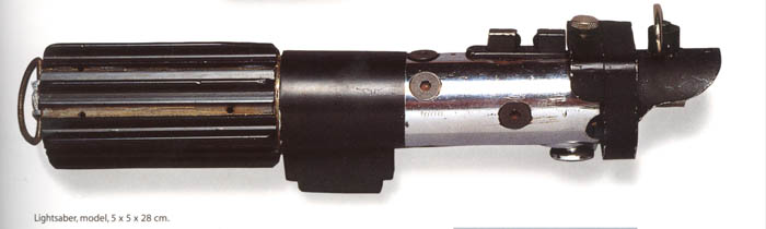
Firstly, here's the Archive pic:

Vader-ROTJ.jpg


Which seems to match up exactly with the famous pic (where's it from again?):

VaderROTJ.jpg


Same pic, enlarged and rotated 180 degrees so it points left:

VaderROTJ-bottom.jpg


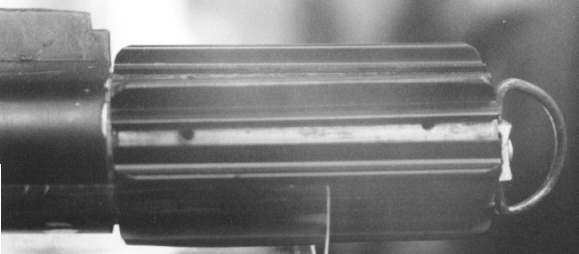
HOWEVER, the holes above there DO NOT MATCH EXACTLY with the following MOM pics:

VaderSaberGrip.jpg


VaderSaberRear2.jpg


Notice that the holes in the former pics are more exposed, whereas the lower pics are closer to and partly covered by the grips.

Perhaps the grips moved?? Dangerous and disturbing this puzzle is.


(5)
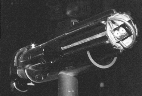
HERE'S THE OTHER WEIRD THING:

The top hole in one of the MOM pics, DISAPPEARED IT HAS!!!!

Now you see it:

VaderSaberGrip.jpg


Now you don't:

Vader-ROTJ-no-hole.jpg


A thought, anyone? (OK, OK, no more Yoda quotes, I promise...
icon_smile.gif
)

Or maybe the answer is.... YET ANOTHER OPTICAL ILLUSION!!!
icon_biggrin.gif
icon_biggrin.gif
icon_biggrin.gif


What do you guys make of the above???
 
I generally agree with everything you are saying about the holes in the lower half. I've done them myself, based on the correct placement of the ranch saber screws and I came out with what all the pics I could find are showing. No problem or trying different times to make it look right. First time worked like a charm.

But I don't think the hole disappeared in the last photo you posted. If you look at the spot where the hole is supposed to be you will see that the entire bottom half has rotated slightly and the presence of a light colored smudge. I think that smudge is just the hole at an angle...
 
</SPAN><TABLE BORDER=0 ALIGN=CENTER WIDTH=85%><TR><TD CLASS=$row_color>
Ghost Host wrote:
<HR></TD></TR><TR><TD CLASS=$row_color>

But I don't think the hole disappeared in the last photo you posted. If you look at the spot where the hole is supposed to be you will see that the entire bottom half has rotated slightly and the presence of a light colored smudge. I think that smudge is just the hole at an angle...
</TD></TR><TR><TD><HR></TD></TR></TABLE>

I think you're right. I think the edge of the transparent plastic stand caused on optical illusion
icon_smile.gif
that obscured the hole, which is actually the light smudge there.

Vader-ROTJ-no-hole.jpg


<TABLE BORDER=0 ALIGN=CENTER WIDTH=85%><TR><TD CLASS=$row_color>
Ghost Host wrote:
<HR></TD></TR><TR><TD CLASS=$row_color>
I've done them myself, based on the correct placement of the ranch saber screws and I came out with what all the pics I could find are showing.
</TD></TR><TR><TD><HR></TD></TR></TABLE><SPAN CLASS=$row_color>

I'm looking for Ranch saber pics where I can see where the rivets were applied. I only have PoSW one, which I can't tell much from.

Any more pics you could post? (I could host them if you want.)
 
Interesting also to note that the diameter of the holes in the handle appears to be similar (if not the same). On the Wampa/Hoth Saber the upper screws are smaller aren't they? Does this hold true for the Ranch saber as well? Or am I suffering from another optical illusion?

Dave C
 
</SPAN><TABLE BORDER=0 ALIGN=CENTER WIDTH=85%><TR><TD CLASS=$row_color>
Oohyeah KL wrote:
<HR></TD></TR><TR><TD CLASS=$row_color>

Notice that the holes in the former pics are more exposed, whereas the lower pics are closer to and partly covered by the grips.

Perhaps the grips moved?? Dangerous and disturbing this puzzle is.

</TD></TR><TR><TD><HR></TD></TR></TABLE><SPAN CLASS=$row_color>

Hmm, it does look like the grip has been re-placed or moved during handling.

Also, looking at the orientation of the D-ring and grips, this pic shows the dring pointing to the 7:30 position and you ocan see thin layer of tube above the grip that is contacting the holes
VaderSaberRear2.jpg


and then here the d-ring is almost horizontal (8-8:30ish) and you can barely see any tube over above the same grip.
VaderSaberGrip.jpg


Or to highlight it a different way, the front grip hole in the lower pic is pretty much along the centerline of the tube ( looking directly across it ) and in the top shop the front hole is lower down the side.

... I just reread the last couple posts and GhostHost made this point already
icon_wink.gif


But, while I looking at the shots I noticed this

Control-Box-comparison.jpg


The SW Insider shot shows the control box with a perfectly flat control box/ switch, but in the MOM photos the surface has a cut or bevel toward the back.

As far as the grip screws, the only shot I have ever seen of the Ranch Version is the POSW shot. But I always got the impression the front screws were smaller. I know several here have done alot of research on that saber and prob have more detailed info ( Gav?)
 
Back
Top