You are using an out of date browser. It may not display this or other websites correctly.
You should upgrade or use an alternative browser.
You should upgrade or use an alternative browser.
HMS Pegasus, 1776
- Thread starter orthofox
- Start date
My lord this is awesome reading!
I'm not sure which I am enjoying more: the construction of the ship or the deconstruction of your mental faculties.
Really informative and really entertaining.
I'm not sure which I am enjoying more: the construction of the ship or the deconstruction of your mental faculties.
Really informative and really entertaining.
I too have jumped off the deep end and built a plank-on-frame ship model. Many years ago I was given a kit second hand. It was missing most of the instructions and all I had was a piece of the box with a 3" picture of the complete ship. That DID give me the liberty (in my mind) to build it however the hell I wanted to, which I proceeded to do. Inaccurate - absolutely! But fun! It's nice to see one being built properly.
orthofox
Well-Known Member
Affixing the sternpost, or hull planks, I just can't quit you...
When last we 'spoke' I promised that this installment would be all about "getting our red on"...whatever that elusive little phrase was intended to mean. And we will, in fact, be "getting our red on" very soon. But not just yet. As I'm trying my best to lay out this build in proper step wise fashion to assist anyone else who also wants to trip the light fantastic in the virtual Chatham dockyards of 18th century England, I need to introduce everyone to the fascinating world of the sternpost.
"What is the sternpost?" you are asking with gleeful anticipation. Well, dear readers, come with me into the fascinating world of one of the most interesting pieces of this build! Let's unravel the mystery of this oddly named member together: As incredible as this may seem, the sternpost is a post that, wait for it............lives at the stern.
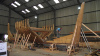
I know the excitement of this revelation is probably making it difficult to concentrate, but I beg you to stay with me just a bit longer. In the normal construction of a ship, the sternpost would have actually been one of the first pieces erected, as it should be attached to the keel by way of an elaborate number of smaller pieces that fashion what is referred to as the deadwood. And this would all potentially happen before any of the frames were positioned as can be seen in this photo:

This sternpost can be seen leaning or raked slightly aft. It rests directly upon the keel. It serves as the termination point of the planks of the hull and is the element upon which the transom rests. It is also the structure upon which the rudder will eventually be attached.
In this photo you can see the real stern post of the HMS Victory, the flagship of the Battle of Trafalgar helmed by Lord Horatio Nelson.

[URL='https://flic.kr/p/2eRcqMJ']
As you can see, the hull planks need to butt up against the sternpost tightly and lie flush with it. It is then anchored to the hull externally with the elongated straps of the hinge that will secure the rudder, called the gudgeons. We'll discuss those in more detail when I place the rudder.
The order in which the sternpost is attached, is therefore quite different with the model, as this step is coming well after the hull planks have all been attached. I believe the reason for this is to make planking the hull much easier. Placing the planks results in them crisscrossing themselves at the stern, and trimming them flush aftward would have been a nightmare with the strenpost in place.
So at this point, I just needed to affix the walnut stern to the MDF keel upon which my hull was fabricated. This actually was a little more problematic than what it appears owing to the fact that quite a bit of glue and sawdust concretions had built up along this stretch of MDF. But, after some judicious filing and sculpting, she found her home and was secured with some PVA glue.


https://flic.kr/p/2eRdZvC
What these photos don't show is that my hull planks are not sitting completely flush with the stern post. They are ever so slightly wider than the post where they meet with it. I was worried about this. If I can't get those planks sanded down more, then the copper plating and the hinges will not sit right on the post and hull and will look goofy as hell. So, despite me being done with the hull planks, the hull planks apparently aren't done with me yet.
https://flic.kr/p/2eRdZvC
Next up: Ok - NOW, let's get our red on![/url]
When last we 'spoke' I promised that this installment would be all about "getting our red on"...whatever that elusive little phrase was intended to mean. And we will, in fact, be "getting our red on" very soon. But not just yet. As I'm trying my best to lay out this build in proper step wise fashion to assist anyone else who also wants to trip the light fantastic in the virtual Chatham dockyards of 18th century England, I need to introduce everyone to the fascinating world of the sternpost.
"What is the sternpost?" you are asking with gleeful anticipation. Well, dear readers, come with me into the fascinating world of one of the most interesting pieces of this build! Let's unravel the mystery of this oddly named member together: As incredible as this may seem, the sternpost is a post that, wait for it............lives at the stern.
I know the excitement of this revelation is probably making it difficult to concentrate, but I beg you to stay with me just a bit longer. In the normal construction of a ship, the sternpost would have actually been one of the first pieces erected, as it should be attached to the keel by way of an elaborate number of smaller pieces that fashion what is referred to as the deadwood. And this would all potentially happen before any of the frames were positioned as can be seen in this photo:
This sternpost can be seen leaning or raked slightly aft. It rests directly upon the keel. It serves as the termination point of the planks of the hull and is the element upon which the transom rests. It is also the structure upon which the rudder will eventually be attached.
In this photo you can see the real stern post of the HMS Victory, the flagship of the Battle of Trafalgar helmed by Lord Horatio Nelson.
[URL='https://flic.kr/p/2eRcqMJ']
As you can see, the hull planks need to butt up against the sternpost tightly and lie flush with it. It is then anchored to the hull externally with the elongated straps of the hinge that will secure the rudder, called the gudgeons. We'll discuss those in more detail when I place the rudder.
The order in which the sternpost is attached, is therefore quite different with the model, as this step is coming well after the hull planks have all been attached. I believe the reason for this is to make planking the hull much easier. Placing the planks results in them crisscrossing themselves at the stern, and trimming them flush aftward would have been a nightmare with the strenpost in place.
So at this point, I just needed to affix the walnut stern to the MDF keel upon which my hull was fabricated. This actually was a little more problematic than what it appears owing to the fact that quite a bit of glue and sawdust concretions had built up along this stretch of MDF. But, after some judicious filing and sculpting, she found her home and was secured with some PVA glue.
https://flic.kr/p/2eRdZvC
What these photos don't show is that my hull planks are not sitting completely flush with the stern post. They are ever so slightly wider than the post where they meet with it. I was worried about this. If I can't get those planks sanded down more, then the copper plating and the hinges will not sit right on the post and hull and will look goofy as hell. So, despite me being done with the hull planks, the hull planks apparently aren't done with me yet.
https://flic.kr/p/2eRdZvC
Next up: Ok - NOW, let's get our red on![/url]
Attachments
Last edited:
I was so surprised, NAY! Shocked at the revelation that the sternpost was at the..... um, ...stern of the ship. I can't wait for more!
")
orthofox
Well-Known Member
That's just bulwarks!
For this phase of the build, we return topside and will be working on some elements that will be highly visible once the entire build is complete. And, these elements will include my first foray into adding some color - specifically, red. Now the instructions give some recommendations as to what shade of red to use - but unfortunately it is a mix of two colors, which will be potentially problematic if I use acrylics. The reason being is that acrylics have a tendency to dry rather quickly, and I'm worried about the ability to appropriately mix the exact same shade of red for all future elements that will require it. The entire issue is further complicated by the dearth of source material with which to use for color matching. No Swan class sloops still exist, and obviously they were built in a time long before color photos. That said, I do have a contemporaneous painting of Pegasus' sister HMS Kingfisher which shows her in all of her brilliant color.

Now, I will not be recreating this entire color scheme for Pegasus, as notes actually do exist on which parts were painted which colors. But I think I can use this painting to help color match the red. After buying many different shades from many different companies and painting many different paint strips and examining those in many different types of light (natural daylight, incandescent and fluorescent), this is what I finally settled on, for better or for worse:
Winsor & Newton Crimson:

So, the specific part I will be working on is the interior planking of the bulwarks along the waist of the ship - where the tops of the frames were removed and the deck was planked over. As with everything else, the specific components of these planks are named.

The first plank is called the waterway (which is also sort of the last deck planking). This is numbered (22) on the diagram. The waterway would help divert water on the deck to channels called scuppers, to usher it off the deck to minimize the amount of swamping.
Above this is number (23), the spirketting. This is a slightly thicker solitary plank that runs just above the waterway.
Above this is the lining or quickworks (24). These are the planks that make up the bulk of the inner bulwark. They, like planking in some other areas, were called quickworks because they could be laid in quicker fashion as they didn't need to be fit so precisely and were not caulked.
The Victory model doesn't come with three separate stock thicknesses of planking to fashion the three different layers, so I tried to fashion my own. The waterway was made from some 1.5mm square basswood, lightly beveled on one corner, while the spirketting and quickworks were made from the 1x4mm walnut used on the hull. The spirketting and waterway planks were primed and pre-painted before placing to prevent me from having to mask the deck and ensuring a nice clean paint line.

Then, the primed quickworks were laid, being careful to cut each one around the gunports and sweep ports as I had to do on the outside of the bulwarks.

Once the lining was completed to the top, the instructions suggested painting the interior of the gunport frame the same color red. However with three different layers now comprising the frame (the quickworks, the ply gunport form and the outer hull planking) I'm worried that this will look like crap.

So I strayed from the directions and primed and painted a couple of left over strips of the deck planking stock, 0.5x3mm tanganyika, and used this to fashion frames for each and every gun port.


This really gives them a much more finished look and was worth the extra effort. Still, with the much smaller sweep ports, I did fink out and just painted the interior red without frames and hope they are small enough that it won't be that noticeable. As each is only 3.3mm across, I think it will be fine - at least that is what i keep telling myself.
The entirety of the inner bulwarks does not need to be planked and painted as at the fore and aft of the ship, the linings will never be seen. They are covered by the forecastle and quarter decks respectively. But I need to extend the painted lining planks just far enough both fore and aft from the waist that those portions that might be seen underneath the second tier decks will look identical to what will be seen along the waist. This was easy to do forward, but working toward the stern, I immediately encountered a problem. To appropriately apply the waterway, spirketting and linings, I first needed to place a deck beam (number 38) that sits at the front of the quarterdeck. This is one of the many horizontal beams that will support the upper decks. BUT, to place deck beam #38, I first need to place the main mast rear bitts, which is essentially a couple of upright posts with a cross-member that are used to secure various lines (we'll discuss those later on). Remember way back at the beginning when I said you have to look 5 steps ahead with everything you do? This is a prime example.
So, I constructed the main mast rear bitts first, and got them primed and painted a burnt umber.

Next up, I again referred to the master plans to ensure they were placed in the right spot, just under deck beam 38.

The two uprights of the bitt slid into pre-cut holes in the main deck - those same holes I had to be careful to plank around while maintaining their appropriate shape and size to make sure there was a tight fit around their base with no gapping.

(Again, I'm sort of glossing over what the bitts are used for in this post. I'll be placing many, many more of these over the course of the build so will do a more complete discussion of their purpose later.)
With the main mast rear bitts in place, deck beam 38 could be placed, primed and painted.

The interior of the planking could then be continued aft of the beam in the same fashion.

I should note that all the planking required a full 4 coats of the crimson red for the color to be true. The grey primer had a strong tendency to show through the first several coats of crimson and give the planks a resulting purple hue which finally was overcome with the 4th coat.
But the final result is acceptable, I think.

So for the next step, I've got several different directions I am considering. Although the kit doesn't include a ship's stove, I'm thinking of scratch building one - as this is a key element to any ship-of-war that was at sea for extended periods, and it would just be visible under the forecastle. Plus, some of the best scenes from Master and Commander involve ship's steward, cranky Killick working at the stove. Also, I need to build and place the wale to go on the exterior of the hull. But before I can do that, I have to complete the sanding of the hull exterior and finish it with some type of treatment. All of this is to say, I'm procrastinating working on the hull again and trying to find an excuse not to dick with it at the moment...
Next up: Let's build a stove!
For this phase of the build, we return topside and will be working on some elements that will be highly visible once the entire build is complete. And, these elements will include my first foray into adding some color - specifically, red. Now the instructions give some recommendations as to what shade of red to use - but unfortunately it is a mix of two colors, which will be potentially problematic if I use acrylics. The reason being is that acrylics have a tendency to dry rather quickly, and I'm worried about the ability to appropriately mix the exact same shade of red for all future elements that will require it. The entire issue is further complicated by the dearth of source material with which to use for color matching. No Swan class sloops still exist, and obviously they were built in a time long before color photos. That said, I do have a contemporaneous painting of Pegasus' sister HMS Kingfisher which shows her in all of her brilliant color.
Now, I will not be recreating this entire color scheme for Pegasus, as notes actually do exist on which parts were painted which colors. But I think I can use this painting to help color match the red. After buying many different shades from many different companies and painting many different paint strips and examining those in many different types of light (natural daylight, incandescent and fluorescent), this is what I finally settled on, for better or for worse:
Winsor & Newton Crimson:
So, the specific part I will be working on is the interior planking of the bulwarks along the waist of the ship - where the tops of the frames were removed and the deck was planked over. As with everything else, the specific components of these planks are named.
The first plank is called the waterway (which is also sort of the last deck planking). This is numbered (22) on the diagram. The waterway would help divert water on the deck to channels called scuppers, to usher it off the deck to minimize the amount of swamping.
Above this is number (23), the spirketting. This is a slightly thicker solitary plank that runs just above the waterway.
Above this is the lining or quickworks (24). These are the planks that make up the bulk of the inner bulwark. They, like planking in some other areas, were called quickworks because they could be laid in quicker fashion as they didn't need to be fit so precisely and were not caulked.
The Victory model doesn't come with three separate stock thicknesses of planking to fashion the three different layers, so I tried to fashion my own. The waterway was made from some 1.5mm square basswood, lightly beveled on one corner, while the spirketting and quickworks were made from the 1x4mm walnut used on the hull. The spirketting and waterway planks were primed and pre-painted before placing to prevent me from having to mask the deck and ensuring a nice clean paint line.
Then, the primed quickworks were laid, being careful to cut each one around the gunports and sweep ports as I had to do on the outside of the bulwarks.
Once the lining was completed to the top, the instructions suggested painting the interior of the gunport frame the same color red. However with three different layers now comprising the frame (the quickworks, the ply gunport form and the outer hull planking) I'm worried that this will look like crap.
So I strayed from the directions and primed and painted a couple of left over strips of the deck planking stock, 0.5x3mm tanganyika, and used this to fashion frames for each and every gun port.
This really gives them a much more finished look and was worth the extra effort. Still, with the much smaller sweep ports, I did fink out and just painted the interior red without frames and hope they are small enough that it won't be that noticeable. As each is only 3.3mm across, I think it will be fine - at least that is what i keep telling myself.
The entirety of the inner bulwarks does not need to be planked and painted as at the fore and aft of the ship, the linings will never be seen. They are covered by the forecastle and quarter decks respectively. But I need to extend the painted lining planks just far enough both fore and aft from the waist that those portions that might be seen underneath the second tier decks will look identical to what will be seen along the waist. This was easy to do forward, but working toward the stern, I immediately encountered a problem. To appropriately apply the waterway, spirketting and linings, I first needed to place a deck beam (number 38) that sits at the front of the quarterdeck. This is one of the many horizontal beams that will support the upper decks. BUT, to place deck beam #38, I first need to place the main mast rear bitts, which is essentially a couple of upright posts with a cross-member that are used to secure various lines (we'll discuss those later on). Remember way back at the beginning when I said you have to look 5 steps ahead with everything you do? This is a prime example.
So, I constructed the main mast rear bitts first, and got them primed and painted a burnt umber.
Next up, I again referred to the master plans to ensure they were placed in the right spot, just under deck beam 38.
The two uprights of the bitt slid into pre-cut holes in the main deck - those same holes I had to be careful to plank around while maintaining their appropriate shape and size to make sure there was a tight fit around their base with no gapping.
(Again, I'm sort of glossing over what the bitts are used for in this post. I'll be placing many, many more of these over the course of the build so will do a more complete discussion of their purpose later.)
With the main mast rear bitts in place, deck beam 38 could be placed, primed and painted.
The interior of the planking could then be continued aft of the beam in the same fashion.
I should note that all the planking required a full 4 coats of the crimson red for the color to be true. The grey primer had a strong tendency to show through the first several coats of crimson and give the planks a resulting purple hue which finally was overcome with the 4th coat.
But the final result is acceptable, I think.
So for the next step, I've got several different directions I am considering. Although the kit doesn't include a ship's stove, I'm thinking of scratch building one - as this is a key element to any ship-of-war that was at sea for extended periods, and it would just be visible under the forecastle. Plus, some of the best scenes from Master and Commander involve ship's steward, cranky Killick working at the stove. Also, I need to build and place the wale to go on the exterior of the hull. But before I can do that, I have to complete the sanding of the hull exterior and finish it with some type of treatment. All of this is to say, I'm procrastinating working on the hull again and trying to find an excuse not to dick with it at the moment...
Next up: Let's build a stove!
Last edited:
PHArchivist
Master Member
I own this...


Build it, build it, build it....
Join the insanity!
orthofox
Well-Known Member
I own this...
Welcome to Ship Builders Anonymous, Mr. Archivist. As you know, admission of your ownership of a model kit of an 18th century British ship-of-war is the first step to getting some help. Some questions:
Do you find yourself replying in the affirmative to random questions with “Aye?”
Have you ever, in a moment of stress, risen to your feet and declared, “We shall beat to quarters!”
Do you have inexplicable urges to use terms like ‘futtock,’ ‘mizzenmast,’ and ‘fo’c’sle’ for no apparent reason?
It’s OK if you answered ‘Aye’ to any of these questions. We’re here to help. The first step is to lay the keel of the Surprise and start erecting this work of beauty. It’s a crime to leave her unassembled in that box...that cardboard coffin.
Let her live, Master Archivist! Let fly!
PHArchivist
Master Member
Welcome to Ship Builders Anonymous, Mr. Archivist. As you know, admission of your ownership of a model kit of an 18th century British ship-of-war is the first step to getting some help. Some questions:
Do you find yourself replying in the affirmative to random questions with “Aye?”
Have you ever, in a moment of stress, risen to your feet and declared, “We shall beat to quarters!”
Do you have inexplicable urges to use terms like ‘futtock,’ ‘mizzenmast,’ and ‘fo’c’sle’ for no apparent reason?
It’s OK if you answered ‘Aye’ to any of these questions. We’re here to help. The first step is to lay the keel of the Surprise and start erecting this work of beauty. It’s a crime to leave her unassembled in that box...that cardboard coffin.
Let her live, Master Archivist! Let fly!
--Aye... To the question regarding "Aye"...
--Learned the expression “...beat to quarters!” (and that it was not BE to quarters!") from the masterpiece that is Master & Commander
--Have engaged the failsafe / overload protection feature of my 7.1 amplifier with only Cast Away (plane crash), and - allow me to say again - the masterpiece that is Master & Commander
--Have, and always, will lament that no more of the duly respected O'Brien's works shall be transformed into cinematic gold...
--A spherical globe masquerading as a fictional battle station (90% complete) stands resolutely in the way of any future creative endeavours
Hi.
My name is John, ("Hi John")
and I have a wooden ship model.... ("be brave...")
This is my second wooden ship model - I think I might be an addict? ("We're all addicts here - no judgement")
Ok then.....
Here is one that I started 10 years ago, but stalled out on. I'm gonna get back to it, and Orthofox is inspiring me.
This is a 1/24th scale model of the Black Pearl. The parts were laser cut from the original 1/6th scale ILM files, but scaled down.
With requisite beer bottle scale comparison on deck. She's a big one!
PHArchivist
Master Member
Love the Pearl, Mate...
And Blue Moon is most certainly a respectable brew...
And Blue Moon is most certainly a respectable brew...
Arr! Scurvy dogs!
orthofox
Well-Known Member
The Stove
Captain of the HMS Surprise, Captain Jack Aubrey, "Killick, Killick there! What do you have for us tonight?"
Ship's cook, Killick, "Which it is soused hog's face."
Captain Jack, ears ringing from an afternoon of target training with the crew on the ships cannons, "Eh?"
Killick, "WHICH IT IS SOUSED HOG'S FACE!"
Aubrey, "My favourite!"

(A still from Master and Commander, I'm pretty sure this is not soused hog's face but rather toasted cheese, which I personally would prefer, but to each her/his own.)
So, in order to avoid dealing with the issues of the stern ends of my hull planking not being tapered enough to the stern post, and still needing to treat the hull planks somehow, and the necessity of applying the ship's wale, I'm doing what any self-respecting modeler would do and procrastinating with a different project altogether - scratch building a stove for HMS Pegasus. The Victory model doesn't provide a stove, and really makes no mention of it at all. But because it is such an important part of any period ship-of-war and the fact that where it is located on the Pegasus, its absence could be noticed by the careful observer, I've decided my Pegasus needs one.
In doing some online sleuthing, I found the original construction plans for the Pegasus and found where the stove was actually drawn in between the knee braces of the forward riding bitts underneath the forecastle.

In this drawing, one can make out the characteristic four-sided beveled funnel at the aft end of the stove, but it is still devoid of real detail. So, I did a bit more research to get a feel of what a stove would look like in an 18th century ship of war and found an excellent example from the HMS Trincomalee, still in existence:

Using this and some further references from the aforementioned book on the scratch building of the Pegasus by Dr. Herbert, I set about drawing up my own plans based on the scale of the Victory model. I knew it had to fit between the long braces of the riding bitts, and match up with the hole in the forecastle deck which accommodates the chimney, but yet not sit too far forward such that it would encroach upon two other holes in the deck which will be utilized for additional elements yet to be placed. So, using these parameters, I made my design and determined the appropriate dimensions of the stove:

The next step was to decide how to build the stove. One possibility was to model it in CAD software and 3D print it. This is a skill I've not yet learned, but having recently gotten a printer, I've been itching for just such a project. But, not wanting to get derailed down a completely different rabbit hole, I ultimately decided to scratch build the stove out of styrene and a few kit-bashed parts. This is what I ultimately came up with:

The styrene tube I used for the chimney atop the funnel is too large, but I chose to use it anyway as I needed a cylindrical element whose internal diameter (5.5mm) will receive the outer diameter (5.0mm) of the chimney that will be visible as it penetrates the forecastle. So, while not being entirely accurate, I think this should work fine.
So the stove was primed with grey primer and then painted flat black with some silver elements on the large pot and pan which rest in the aft part of the stove. To give some reference as to the size of the stove, I photographed it alongside an American quarter:

(My next model is definitely going to be a larger scale.)
Next up, I temporarily dry-fit the riding bitts and the stove to ensure everything fit:


This was a fun little diversion from the stressful endeavor that the hull planking has become and to which I must return next time if I'm to move this project forward. Fortunately there is ALWAYS something with which to distract myself, and I'm excited to share with you the project of a real shipwright that I stumbled upon this past weekend which has re-calibrated my own woes dramatically. But that will have to wait until next time, so stay tuned.
Next up: Boil, boil trouble and toil.
Captain of the HMS Surprise, Captain Jack Aubrey, "Killick, Killick there! What do you have for us tonight?"
Ship's cook, Killick, "Which it is soused hog's face."
Captain Jack, ears ringing from an afternoon of target training with the crew on the ships cannons, "Eh?"
Killick, "WHICH IT IS SOUSED HOG'S FACE!"
Aubrey, "My favourite!"
(A still from Master and Commander, I'm pretty sure this is not soused hog's face but rather toasted cheese, which I personally would prefer, but to each her/his own.)
So, in order to avoid dealing with the issues of the stern ends of my hull planking not being tapered enough to the stern post, and still needing to treat the hull planks somehow, and the necessity of applying the ship's wale, I'm doing what any self-respecting modeler would do and procrastinating with a different project altogether - scratch building a stove for HMS Pegasus. The Victory model doesn't provide a stove, and really makes no mention of it at all. But because it is such an important part of any period ship-of-war and the fact that where it is located on the Pegasus, its absence could be noticed by the careful observer, I've decided my Pegasus needs one.
In doing some online sleuthing, I found the original construction plans for the Pegasus and found where the stove was actually drawn in between the knee braces of the forward riding bitts underneath the forecastle.
In this drawing, one can make out the characteristic four-sided beveled funnel at the aft end of the stove, but it is still devoid of real detail. So, I did a bit more research to get a feel of what a stove would look like in an 18th century ship of war and found an excellent example from the HMS Trincomalee, still in existence:
Using this and some further references from the aforementioned book on the scratch building of the Pegasus by Dr. Herbert, I set about drawing up my own plans based on the scale of the Victory model. I knew it had to fit between the long braces of the riding bitts, and match up with the hole in the forecastle deck which accommodates the chimney, but yet not sit too far forward such that it would encroach upon two other holes in the deck which will be utilized for additional elements yet to be placed. So, using these parameters, I made my design and determined the appropriate dimensions of the stove:
The next step was to decide how to build the stove. One possibility was to model it in CAD software and 3D print it. This is a skill I've not yet learned, but having recently gotten a printer, I've been itching for just such a project. But, not wanting to get derailed down a completely different rabbit hole, I ultimately decided to scratch build the stove out of styrene and a few kit-bashed parts. This is what I ultimately came up with:
The styrene tube I used for the chimney atop the funnel is too large, but I chose to use it anyway as I needed a cylindrical element whose internal diameter (5.5mm) will receive the outer diameter (5.0mm) of the chimney that will be visible as it penetrates the forecastle. So, while not being entirely accurate, I think this should work fine.
So the stove was primed with grey primer and then painted flat black with some silver elements on the large pot and pan which rest in the aft part of the stove. To give some reference as to the size of the stove, I photographed it alongside an American quarter:
(My next model is definitely going to be a larger scale.)
Next up, I temporarily dry-fit the riding bitts and the stove to ensure everything fit:
This was a fun little diversion from the stressful endeavor that the hull planking has become and to which I must return next time if I'm to move this project forward. Fortunately there is ALWAYS something with which to distract myself, and I'm excited to share with you the project of a real shipwright that I stumbled upon this past weekend which has re-calibrated my own woes dramatically. But that will have to wait until next time, so stay tuned.
Next up: Boil, boil trouble and toil.
Last edited:
Just. Fun. Reading.
orthofox
Well-Known Member
Wale Tales
The time has finally come to address the issues with the hull exterior once and for all. The first step was to taper the stern ends of the hull planking down even more so that their ultimate thickness (port to starboard) would match that of the stern post. I wish now that when I was fashioning the bearding line on the central false keel MDF that I had been more aggressive so that the first layer of planking was recessed below the level of the stern post such that the second layer of planking would be flush with it. But I wasn't and now I have bulging stern planks. Nobody wants bulging stern planks. Chalk this up as yet another rookie mistake.
But there's nothing to be done for it other than trying to taper these planks down. I started aggressively with a tiny finger plane.

This was followed by more sanding with 220 grit until the inevitable finally happened:

I took the 2nd layer planking down to such a thickness that the feathered edge was starting to break free, and I knew I couldn't take it down any further. At this point, it is what it is. So if you notice my stern planking bulge a bit, be kind and don't mention it, OK? Just move along...
So the next decision was how to treat the walnut second planking. I needed to do something to enrich and protect the planks. Never being much of a fan of stains, and worried that staining the planking could actually accentuate blemishes and scars left from shaping and sanding and handling the hull, I decided to go with boiled linseed oil.

Never having used this before, I poured some into a clean container and stained a couple of plank cut-offs with it to test it out.

(And yes, I am wearing black tights in this photo, and no that's not because I'm secretly a ballet dancer. I had just gotten back from a run and it is colder than a proverbial witch's breast in a brass brazier here, hence the necessity for full leg coverage. Now is no time for frostbite. I've got a ship to build!)
Using a clean, lint free cloth, I applied the oil to the entirety of the ship's hull. The wood soaked it in quickly, but I still wiped any excess free after a couple of minutes. And, after 2 applications, I was happy with the outcome, despite the Pegasus smelling a bit like a broccoli salad. Here you can see the before and after:

It definitely darkened the wood, made the walnut a more rich color and gave it a very subtle matte sheen finish. All-in-all I was pretty happy with the outcome - I just hope the smell goes away because I really, really hate broccoli.

(Don't judge me because my 3D printed Chachopoyan fertility idol is not yet painted gold. I've been busy.)
And with the hull finally treated, it was time to put the wale on.
The wale is a thick single strake, or belt of strakes located along the sides of the vessel that help gird it and stiffen the hull. They reside at the widest portion of the hull, and in that way also provide some protection - like a bumper of sorts. It may not be readily apparent but above the level of the wale, toward the sheer, or top-most strake, the walls of the ship actually curve inward. In other words, the top of the ship is narrower than it is halfway to the water line. This inward curvature is called the tumblehome of a ship and improves her stability by reducing topside weight.
Comprised of three strakes, the wale on the Pegasus is fairly wide, top to bottom, and is black. So this is a very obvious aesthetic feature of the final appearance of the ship, and thus needs to be absolutely perfect. And by perfect, I mean, its location from top to bottom and port to starboard has to be positioned in the exact right spot to allow for the securing of a number of additional rigging elements that are yet to come. Thus, I was a bit nervous about my ability to get this just right having absolutely no idea what I was doing. The plans, shockingly, give excruciatingly little detail as to the proper location of the wales, simply stating to make them match the construction plans. Helpful. So, as with most of the build, I started to do some sleuthing and referred all the way back to the construction plans of the original Pegasus - since, after all, that is what I'm trying to replicate here. On this particular image, I've artificially colored the wale black so everyone can see what and where it is.

My idea was to use the original plans and measure the distance between the top edge of the wale and the bottom edge of the gun ports at each station and transfer those dimensions to the ship. So, step one was to print off a copy of the Pegasus' original construction plans found online. (You can also order a high-res copy for 25 pounds from England, but I didn't feel like waiting for those to arrive). So what resulted was a lower resolution copy that I assembled trying to match the size of the originals I found online.

The obvious problem is that my model is larger than the construction plans. So, I took a number of measurements of various other parts of the model I had assembled (dimensions of the gunports, sweep ports, stern post, etc) and compared those to the construction plans to arrive at a magnification factor to determine just how much bigger my model is versus the printed plans: It was 1.4X larger.
Next up, I measured the distance from the bottom of each of the gunports on the plans to the wale (marked in red in this photograph).

Each of these values was recorded and multiplied by the magnification factor, and then transferred to the model, making a very small mark in pencil to establish the wale line.

This left with me tick marks below each and every gun port, and similar references on the prow and at the stern. Now, this model calls for the wale to be constructed from three 1x4mm walnut planks - the same used for the 2nd hull planking. But they are to be painted black. I didn't want to paint them after they had been secured to the ship, because that would have required me to mask off the hull and risk getting black paint on my newly oiled walnut planks. So, I started by soaking two walnut strakes in hot water for 10 minutes (one for port, one for starboard) and then applied those to the hull using some clamps and rubber bands, to let them conform to the shape of the hull overnight. The next morning, after they had retained their shape, I primed and painted each black. Then, each was applied to the hull of the ship following the tick marks I had made the previous day. There was no way to secure this first wale plank on - clamps would mar it, and pins would leave an unsightly hole. So I put a dab of CA glue at the bow end (or the hood of the strake) to secure it, and then coated the bottom a few centimeters at a time with PVA glue, holding it in place with my fingers until they had set and became secure - first for the port side, and then for the starboard.

The first strake was the hardest, because I only had my light pencil marks to follow, but got both sides done.

The subsequent strakes were treated and applied in similar fashion, but went on much faster and easier since they could ride against the initial wale strake as a guide.

So each was soaked, placed gently with rubber bands to conform it generally to the shape, primed, painted and then secured by hand. And after a full day, all three strakes were secured on each side. I ended up sanding down the edges between the strakes as they want to ride up a bit trying to conform to the curved hull, which required much touch up paint work, but in the end, this is how she came out.


They aren't perfect, by any stretch, and I've identified several subtle errors, but at this point I'm pretty committed and am trying to overlook the mistakes.
So what's next? I have no idea. I'm so far off the directions right now with respect to order of assembly that I need to come up with a game plan. Had I followed the directions, I would have assembled and attached most of the gun deck accoutrement by this point, which is just insane, since I'm turning her over and resting her on her deck so frequently to work on the hull. So, if I follow the notion of finishing the hull entirely before working topside, that would mean the next step is coppering the hull - something I've not even begun to contemplate. I need to weigh out my options before moving forward..
Next up: Choose your own adventure!
The time has finally come to address the issues with the hull exterior once and for all. The first step was to taper the stern ends of the hull planking down even more so that their ultimate thickness (port to starboard) would match that of the stern post. I wish now that when I was fashioning the bearding line on the central false keel MDF that I had been more aggressive so that the first layer of planking was recessed below the level of the stern post such that the second layer of planking would be flush with it. But I wasn't and now I have bulging stern planks. Nobody wants bulging stern planks. Chalk this up as yet another rookie mistake.
But there's nothing to be done for it other than trying to taper these planks down. I started aggressively with a tiny finger plane.
This was followed by more sanding with 220 grit until the inevitable finally happened:
I took the 2nd layer planking down to such a thickness that the feathered edge was starting to break free, and I knew I couldn't take it down any further. At this point, it is what it is. So if you notice my stern planking bulge a bit, be kind and don't mention it, OK? Just move along...
So the next decision was how to treat the walnut second planking. I needed to do something to enrich and protect the planks. Never being much of a fan of stains, and worried that staining the planking could actually accentuate blemishes and scars left from shaping and sanding and handling the hull, I decided to go with boiled linseed oil.
Never having used this before, I poured some into a clean container and stained a couple of plank cut-offs with it to test it out.
(And yes, I am wearing black tights in this photo, and no that's not because I'm secretly a ballet dancer. I had just gotten back from a run and it is colder than a proverbial witch's breast in a brass brazier here, hence the necessity for full leg coverage. Now is no time for frostbite. I've got a ship to build!)
Using a clean, lint free cloth, I applied the oil to the entirety of the ship's hull. The wood soaked it in quickly, but I still wiped any excess free after a couple of minutes. And, after 2 applications, I was happy with the outcome, despite the Pegasus smelling a bit like a broccoli salad. Here you can see the before and after:
It definitely darkened the wood, made the walnut a more rich color and gave it a very subtle matte sheen finish. All-in-all I was pretty happy with the outcome - I just hope the smell goes away because I really, really hate broccoli.
(Don't judge me because my 3D printed Chachopoyan fertility idol is not yet painted gold. I've been busy.)
And with the hull finally treated, it was time to put the wale on.
The wale is a thick single strake, or belt of strakes located along the sides of the vessel that help gird it and stiffen the hull. They reside at the widest portion of the hull, and in that way also provide some protection - like a bumper of sorts. It may not be readily apparent but above the level of the wale, toward the sheer, or top-most strake, the walls of the ship actually curve inward. In other words, the top of the ship is narrower than it is halfway to the water line. This inward curvature is called the tumblehome of a ship and improves her stability by reducing topside weight.
Comprised of three strakes, the wale on the Pegasus is fairly wide, top to bottom, and is black. So this is a very obvious aesthetic feature of the final appearance of the ship, and thus needs to be absolutely perfect. And by perfect, I mean, its location from top to bottom and port to starboard has to be positioned in the exact right spot to allow for the securing of a number of additional rigging elements that are yet to come. Thus, I was a bit nervous about my ability to get this just right having absolutely no idea what I was doing. The plans, shockingly, give excruciatingly little detail as to the proper location of the wales, simply stating to make them match the construction plans. Helpful. So, as with most of the build, I started to do some sleuthing and referred all the way back to the construction plans of the original Pegasus - since, after all, that is what I'm trying to replicate here. On this particular image, I've artificially colored the wale black so everyone can see what and where it is.
My idea was to use the original plans and measure the distance between the top edge of the wale and the bottom edge of the gun ports at each station and transfer those dimensions to the ship. So, step one was to print off a copy of the Pegasus' original construction plans found online. (You can also order a high-res copy for 25 pounds from England, but I didn't feel like waiting for those to arrive). So what resulted was a lower resolution copy that I assembled trying to match the size of the originals I found online.
The obvious problem is that my model is larger than the construction plans. So, I took a number of measurements of various other parts of the model I had assembled (dimensions of the gunports, sweep ports, stern post, etc) and compared those to the construction plans to arrive at a magnification factor to determine just how much bigger my model is versus the printed plans: It was 1.4X larger.
Next up, I measured the distance from the bottom of each of the gunports on the plans to the wale (marked in red in this photograph).
Each of these values was recorded and multiplied by the magnification factor, and then transferred to the model, making a very small mark in pencil to establish the wale line.
This left with me tick marks below each and every gun port, and similar references on the prow and at the stern. Now, this model calls for the wale to be constructed from three 1x4mm walnut planks - the same used for the 2nd hull planking. But they are to be painted black. I didn't want to paint them after they had been secured to the ship, because that would have required me to mask off the hull and risk getting black paint on my newly oiled walnut planks. So, I started by soaking two walnut strakes in hot water for 10 minutes (one for port, one for starboard) and then applied those to the hull using some clamps and rubber bands, to let them conform to the shape of the hull overnight. The next morning, after they had retained their shape, I primed and painted each black. Then, each was applied to the hull of the ship following the tick marks I had made the previous day. There was no way to secure this first wale plank on - clamps would mar it, and pins would leave an unsightly hole. So I put a dab of CA glue at the bow end (or the hood of the strake) to secure it, and then coated the bottom a few centimeters at a time with PVA glue, holding it in place with my fingers until they had set and became secure - first for the port side, and then for the starboard.
The first strake was the hardest, because I only had my light pencil marks to follow, but got both sides done.
The subsequent strakes were treated and applied in similar fashion, but went on much faster and easier since they could ride against the initial wale strake as a guide.
So each was soaked, placed gently with rubber bands to conform it generally to the shape, primed, painted and then secured by hand. And after a full day, all three strakes were secured on each side. I ended up sanding down the edges between the strakes as they want to ride up a bit trying to conform to the curved hull, which required much touch up paint work, but in the end, this is how she came out.
They aren't perfect, by any stretch, and I've identified several subtle errors, but at this point I'm pretty committed and am trying to overlook the mistakes.
So what's next? I have no idea. I'm so far off the directions right now with respect to order of assembly that I need to come up with a game plan. Had I followed the directions, I would have assembled and attached most of the gun deck accoutrement by this point, which is just insane, since I'm turning her over and resting her on her deck so frequently to work on the hull. So, if I follow the notion of finishing the hull entirely before working topside, that would mean the next step is coppering the hull - something I've not even begun to contemplate. I need to weigh out my options before moving forward..
Next up: Choose your own adventure!
Last edited:
Holy Cow! I must have some finger planes now!
After seeing that photo, I immediately Googled finger planes. Too cool!
Would it have made sense to thicken the stern post a little, rather than shaving down the stern planking as far?
Kinda' like: Instead of raising the bridge, lower the river?
Or would that have led to further issues? Like not matching the rudder?(Since we can't read 5 steps ahead on the instructions)
After seeing that photo, I immediately Googled finger planes. Too cool!
Would it have made sense to thicken the stern post a little, rather than shaving down the stern planking as far?
Kinda' like: Instead of raising the bridge, lower the river?
Or would that have led to further issues? Like not matching the rudder?(Since we can't read 5 steps ahead on the instructions
)
Last edited:
Similar threads
- Replies
- 22
- Views
- 820