Functional Pip-boy 3000 Mk IV from Fallout 4

Oh, did I get the wrong part? I got it from the excel spreadsheet checked in to github when i downloaded everything... I'll have to go get an up-to- date copy send see... A 3v led would be much better! Are you driving them with exactly 3.0v (I guess through a voltage divider or a voltage regulator?) or were you letting the 3.3v from the logic drive them?

The part I got, which was what I thought was the closest they had to what I thought I needed is JK2835BWT-W-U30EB0000-N0000001, which is a warm white 6v surface mount.
I may have gotten the idea from the cad drawing and not the BOM. I see it correct in the BOM, with the link encoded in the cell. I was having trouble figuring out how to get the links to come up in my ancient version of excel, so some of the parts I tried to use the name from the cad file. I think I can get these, and see if I can get my son to solder them on the cree footprint. I think the pad spacing is close enough... Otherwise, I can get a 12v step-up converter to go from 5v to 12v, and then get a 6v voltage regulator and put that on the output of the 12v converter :) I don't want to have to re-design the PCBs and get them re-made. I can hack something in there... For the radio gauge, I can remove the resistor, and run another wire to the side that feeds the LEDs and power that with the driver. The ground would be shared. For the rad gauge, the wires for the LEDs aren't shared with anything else, so it should be OK there... Then again, If I can just send the 3.3v from the Arduino to these new LEDs, with a resistor to drop 0.3v assuming 15mA x 3, it would be simpler.
 
I didn’t use a scavenged tape, it wasn’t strong enough. I bought rolls spring steel from McMaster. But even then I don’t consider the design done. I have two different thicknesses to try out. To bend the end of the spring steel over, you have to heat it up to a red hot or it will snap.
Do you have links for any of the ones you tried / wanted to try? I'm coming up to that section in my build now.
 
I don’t remember what sizes of steel I ordered, here is the list on McMaster:
I think I was using the thinner ones.
 
quick question for you: Does your pipboy do anything special when the "accessory" plug is actually plugged in? I'm trying to determine what to do on mine.
 
My initial (and current design) was to use the plug as a USB 2.0 connector. I think when I revisit the project I may convert it into just a two pin charger connection to make the slip-joint simpler.
 
Yeah, that's what I'm doing. I have a bunch of the rotor boards if you want one. I was thinking mainly about what to do on the UI itself when connected. Having it either show the "Vault Door Remote Access" screen like the beginning of Fallout 4, or maybe having it show some sort of Power Armor diagnostic screen... Still working on finding representative graphics for those.
 
The link you had above didn't include anything I could find that would make a clock spring (at least not on the page that came up). I did find this, though, McMaster-Carr It's a little too wide, but is this kind of what you were using?
 
The link you had above didn't include anything I could find that would make a clock spring (at least not on the page that came up). I did find this, though, McMaster-Carr It's a little too wide, but is this kind of what you were using?
That spring is a wind from inside model. I don’t know what strength it is. The spring I made is from spring steel stock. The thickness has to be protested to get the right tension.
Spring Steel

 
That spring is a wind from inside model. I don’t know what strength it is. The spring I made is from spring steel stock. The thickness has to be protested to get the right tension.
Spring Steel

so you rolled your own? That page only shows sheet, bar, or 10' rolls of raw sheet spring steel. Still trying to find "wind from inside"
 
so you rolled your own? That page only shows sheet, bar, or 10' rolls of raw sheet spring steel. Still trying to find "wind from inside"
Yes, I used a torch to heat up the end of the strip to allow it to be bent and make my own spring from flat stock.
 
Hi, I registered my account to say that I have done a bit of rework to this code from your Github to get it to run nicely on a 640x480 screen through a Raspberry Pi. I had this 3D printed model in mind because it's relatively easy to print. To handle the IO, I'm using an Arduino Pro Micro wired to a rotary switch, a rotary encoder, and a push button. The reason I chose an Arduino Pro Micro is that it's using the chipset with a keyboard library, so the Raspberry Pi thinks it's getting keyboard inputs when you operate the dials and buttons on the Pip Boy. For audio, I'm using a basic little Bluetooth audio receiver (The Raspberry Pi 5 doesn't have a physical audio jack) and a powered amplifier connected to one of those little greeting card speakers.

My thinking was that I could make a working Pip Boy that's more beginner friendly and less ambitious than your project, and I'm hoping to release it as a fork. I'll include links to this project.
 
Last edited:
Dude, I am SO glad that this is still living on and being developed! I wish I had known about the discord a couple of months ago, when I picked my own project back up again, though I’m using the CM4 with an 800x480 display.

I want to keep as much of the functionality that you laid out, while simplifying the overall build, so I’m going with FO London’s Atta-Boy design instead.
 
Last edited:
My thinking was that I could make a working Pip Boy that's more beginner friendly and less ambitious than your project, and I'm hoping to release it as a fork. I'll include links to this project.
Doing the same thing. Very slowly. See you on RobCo discord?


Lots of work on the Pip-boy CAD design. Mostly optimizing the design, but I also added a few new features.
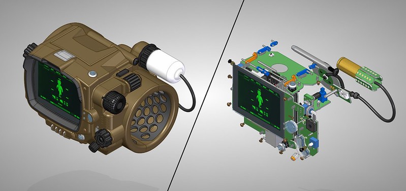
The image above shows just how much stuff is inside the pip-boy.

------------------------


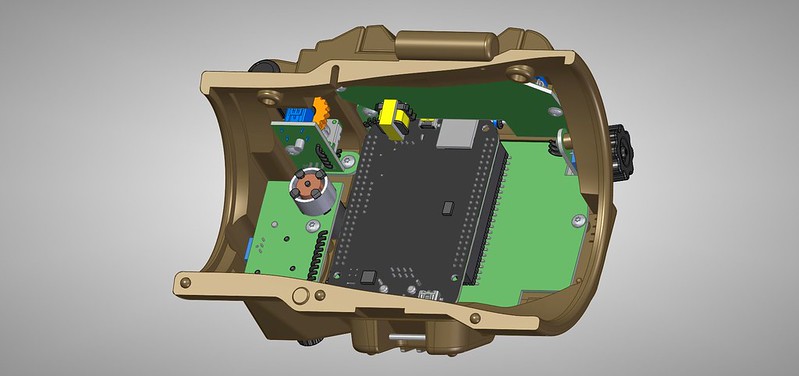
There are 11 PCBs, as well as dozens of hardware components, wires and fasteners. Assembling one of these will take a bit of time and skill. The tolerances between some parts is as small as half a millimeter.

------------------------


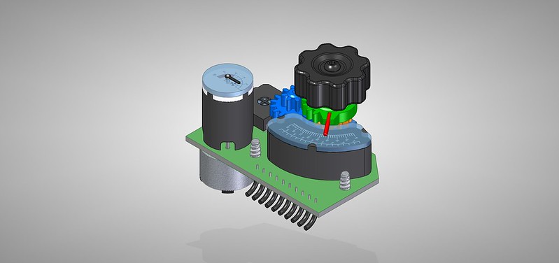
I was able to combine the rad-gauge and radio gauge assemblies into one. The good news is that the motor that runs the rad-gauge is available in low quantities. It costs a few dozen bucks, but allows for actual precise control over the gauge needle. I still haven't found a supplier of watch hands that fit the look I want. The gauge needle may need to be custom cut. I also removed most of the connectors from the PCBs, instead wires or cables will be installed on the small PCBs, and connectors will only be on the larger master PCB. This saves some bulk, weight, and cost.

------------------------


Shown here is the RFID PCB, with a grey disk where the antenna will be located.

The yellow item is a place holder for an audio transformer. This large part would be required for a full geiger counter. However, a full geiger counter is turning out to be a difficult addition to the pip-boy and adds a lot of cost and risk. I think I am going to change to a Pin-Diode type radiation detector. These can detect x-rays and gamma rays, as well as a few other forms of radiation. As cool as having a full geiger counter is, it instantly adds $100 to what will already be an expensive prop. It also adds a 500V circuit, which can be very difficult to contain and control. For example I can't find any 3mm diameter, 4 conductor shielded cable which is even rated for that voltage. Also a full geiger counter is pretty useless in real-life. You can't show it's function off at any Con, unless you want to try to take a uranium sample into a public space. If you had a real geiger counter and it was picking up enough radiation to make the gauge needle even move, you probably should be running away.

A Pin-diode detector would still be a real gamma ray detector, and can be built for just a few dollars. I also will skill keep an IR sensor as a option. At least with an IR temperature sensor you could scan a object and have the gauge show a interactive read-out.
------------------------


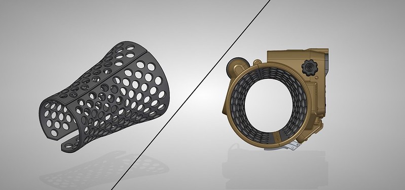
One item of concern in the design is heat, as well as comfort. My friend lent me his Pip-Boy 3000, which he modded from the Pip-Boy clock. Wearing it is a pain unless you have a thick sleeve or padding. So for my Pip-boy design I created a ventilated set of bands which fit into each half of the Pip-boy. These are designed with a round entry and exit, but a elliptical center. The ellipse does two things: It give me more precious room inside for electronics, and it also form fits the Pip-boy around my arm. In this way the Pip-boy shouldn't be prone to rotating around my arm. The center is designed to fit my arm when 1/4" of padding is used. If your arm happens to be larger, then you will need to use less padding. A pattern of vent holes will hopefully keep both the wearer and the electronics cooler, and also allow the bands to flex a bit.

------------------------


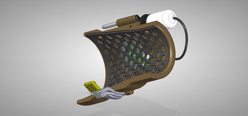
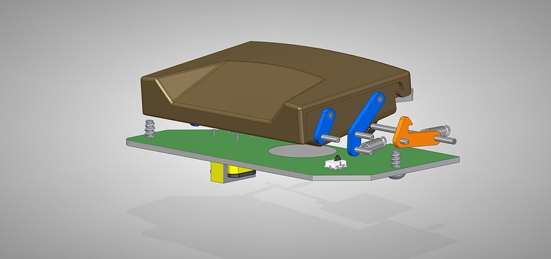
This image shows how the bands snap into each half. It also shows my new latch design in more detail.

------------------------


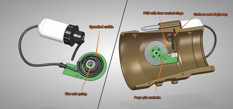
Also on the back is a whole new feature. A re-tractable cable reel. This was difficult to design into a compact size, while maintaining electrical contacts.
The reel uses a constant force spring to tug on the cable at all times, similar to a tape-measure. A 3D printed housing holds the spring to a PCB. The round PCB has four raceways, one for each of the four wires inside the cables. The rectangular PCB has four pogo-pins which bridge the connection between the internal cable, and cable reel. I estimate that a few feet of wire can be kept spooled up inside the pip-boy. The four wires are enough to run the LED lights, as well as a Pin-Diode, or IR sensor.

It is easy to design a one-way cable clamp, however it is more difficult to design one which has some sort of release. Yes, I can add a button or something. But I am trying my best to keep the external look of the Pip-boy accurate to the game, so I don't want to add any extra buttons or levers. I really want a "Tug-to-retract" mechanism, sort of like what is in a old-school vacuum cleaner. But so far I haven't been able to find any diagrams of how these worked, or figure out my own.


Hello zapwizard ,
I wanted to ask if there is a circuit diagram for the electronics so that the circuit board can be rebuilt. I can only find the assembly but not the circuit diagrams of how the tracks have to be on the board.

I would also like to know whether it makes no difference whether I use the BeagleBone Black or the Raspberry Pi 5 in terms of the compatibility of the additional circuit boards or whether everything is compatible with each other.

Kind regards,
LightRO
 
Hello zapwizard,
I wanted to make this and I wanted to know if you had an updated Google Drive document. I have no idea how to mention you but hey a man can try. Do you think you can Include its estimated cost also? That would help a lot.
 
Hello zapwizard,
I wanted to make this and I wanted to know if you had an updated Google Drive document. I have no idea how to mention you but hey a man can try. Do you think you can Include its estimated cost also? That would help a lot.
Do you also have any cost effective options? I want this to run under 200. Because if its above 200 I might as well just purchase the dicast model.
 
I have so many questions yet my main one is, Is the cable a USB so I can connect it to a computer through the USB port???
 
Back
Top