Functional Pip-boy 3000 Mk IV from Fallout 4

First off I appreciate your feedback, and for following the project so closely for all this time.

When I first started the project I researched for hours trying to find a candidate device to cannibalize for its brains and screen.
I setup a spreadsheet with about a dozen candidate devices, but I couldn't find any devices which has a 4:3 3.5" to 3.7" LCD screen. (Everything was 16:9). Even if I found a device that fit, the screen is most likely not on a ribbon cable, and couldn't be re-located, forcing the whole phone to fit behind the screen. Most devices have lots of extra length past the phone. This would break the game accurate shape, and push it into Pip-Boy edition type scaling.

I haven't found any android compatible PCB which has everything needed. The Udoo Neo was so promising, it's only major issue electrically was they used a LVDS screen interface and custom connector. But they haven't released hardly any useable software, I think they hoped to release the device and that their customers would do all the work and post it to their forums. So far people have only been able to get the bare minimum feature working. While the BeagleBone has been on the market for years and I can find all the information will need.

At this point I want to get back into full swing on the project, and I think GhostMinion is right. Get the bare minimum features working. They will be hard enough. Even with the minimum features the build is still far more advanced than what Adafruit or anyone else has built previously. (Okay NASA did pretty good on theirs)

Also, part of this project is to over engineer everything, sort of as an exercise for my own learning. My goal was and still is to design the Pip-Boy as if it were really made by Vault-Tec. I didn't want to wire together 15 different circuit boards and cram it into an enclosure, which is so commonly done on Pi builds. I have already done too many hobby projects in the past that required tons of hot-glue and dremeling. Take my most popular project: My Ammo PC. One of the first gaming PC mods ever made which was a complete transformation, making it unrecognizable as a PC. The front panel looks cool as hell. The backside of that panel however is literally a rats nest of wires and hot-glue.

I think I will simply get cracking on getting one item at a time to work on the electronics. If I do my design right, I can add features in stages. When I first started with the Beaglebone using Python and Ubuntu I was able to get sensor data working the same day I got the board.
 
Last edited by a moderator:
Hey man fair enough! You definitely got your own capabilites to work with as we all do, and so far its been going pretty well! What is the scaling difference on the pipboy collectors edition as opposed to the in-game model out of curiosity? They looked nearly the same to me personally, the CE maybe being a bit bigger but not by much. Or am I way off?

haha I just figured I would throw that option in for ya to confirm it works. Because for me it has all the features of the in-game model with the buttons I want as well as easy accessibility and having the benefit of looking the part perfectly from their factory mold, as well as allowing me to build a relatively straight forward, if not extremely challenging at times, working prop. As always though man, good luck going forward and lemme know if you need any help or anything!
 
The Pip-Boy edition has a few changes compared to the game. Most of them seem to be simply to fit in a phone, or make it easier to manufacture. It has a deeper screen to set the phone deeper into the enclosure. The selection knob is also moved up towards the front, also to clear the phone inside. The Holotape mechanism doesn't go far enough back. The selection wheel doesn't protrude from the corner, it is almost flush. Some of the overall curves and shapes are muted compared to the game. But for a $60 prop it's great.
 
Aaahh gotcha, all very minor things to me personally. When I compare the in-game model to my collector's edition I don't notice any differences except mine is new looking and the game's in old and beat to **** haha. Some details I obsess over, like the correct metallic sheen on the heat sinks. God those things have been driving me crazy..
 
Ok so its been a few weeks since I read the post and I may have something of use (now that the android boot isn't an issue). I completely forgot about one of the kickstarters I backed until i got an email yesterday and it may be of use to you.

C.H.I.P. The $9 Computer
1GHz processor, 512MB ram, 4GB on-board flash memory
Built in B/G/N wifi, bluetooth4.0, native LCD support 4.3-8"
I2C, SPI, UART, and 8x GPIO ports
will run on a single cell Lipo 3.7volt battery for hours (in Pocket Chip aka: 4.3" 470px x 272px screen w/ resistive touch run time of about 4.5 to 5 hours)
Dimensions: 40mm x 60mm (1.5" x 2.3') [think thats smaller that the board your looking at right?]

This board is currently on pre-order and backer kits are shiping over the next 3 months. Pre-orders should start shiping within the year.
If the low amount of ram is an issue the developers say it is posible to swap the 512MB ram chip for a 1GB chip but you must be confident at doing small breadboard soldering (solder paste and a heat gun).

If I'm right and this board is smaller than it could reclaim some space for you and it will not require a step transformer to run on small batteries. Plus it has an on-board charger circut for the batteries it is connected to as well as being dirt cheap.

http://getchip.com/

Hope this info isn't too late to help. Personally I think the non-official versions or the Pip-Boy app that will run on other platforms will work better once the developers (hackers love you guys) figure out all the protocols.
 
I did look at the CHIP a while back. At that time there wasn't any good documentation, it seems to have an amazing amount of documentation listed. It has pins to drive a Parallel LCD screen. It looks very promising, and is a bit smaller. But I will put it into the wait and see category.

The BeagleBone Black runs off 3.3V (unless I need to use the USB host), so no up converter is needed for normal operation.
At this point I need to get cracking on the prototype electronics. Wire up the LCD screen and get some basic stuff running. Before I can do that I have a lot of work to do in my office to get setup to work on electronics.
 
Wow. This is incredible man! And your CAD skills are impressive. Subscribed :D

I'm sure you've said it but this is getting long :p What program are you using?
 
@MisterLamont: First off, thanks. I am using Solid Edge for all the modeling. Not to be confused with Solid Works. Solid Works is great, but Solid Edge is a higher end program.

Okay, this turned into a long-winded sales pitch, but it really has been the best CAD software I have ever used.
Solid Edge has a feature they call "Synchronous modeling", and it really it night and day compared to other CAD programs, as far as modeling power and speed.

Dating back to the first AutoCAD; most CAD programs require you to first make a 2D sketch. Then you could extrude or cut that sketch to make your 3D model. Most CAD programs did this in a step-by-step history tree. They build the model one sketch at a time. If you had to change some portion of the model, you have to literally go back in time in the model tree, make an alteration to the sketch, and then try to have the CAD software re-calculate all the other sketches that came after that. Often this would break downstream sketches.

In the past few years, programs like Solid Works and Creo tried to get away from 100% history based modeling, but they still have one foot stuck in the past, requiring sketches and history-based modeling for many of their core functions.

Solid Edge can be run in a traditional sketch/history based mode, but the real power comes when running in synchronous mode. Basically, you draw a temporary sketch to setup your shape, and then extrude or cut it like with any other CAD software. However, the resulting 3D model isn't tied to the actual sketch in any way. Instead the 3D model just exists on its own. If you want to alter some hole size, or dimension you can literally just select the dimension tool and alter it on the 3D model. The software calcualtes any required changes like tangents or symmetry automatically using constraints and rules. The end result is that you can make models almost like you were sculpting, while still maintaining dimensional accuracy. It become far easier to model exactly what you need, and less a fight with the CAD software to get an end result. It would have taken me at least ten times as long to model the Pip-Boy in another program, and I would have hesitated to re-build the model. (I have rebuilt it from scratch 3 times on this project)

Also, for the sake of honesty here are the programs I have used in the past:
-Solid Edge: Amazing to use.
-Solid Works: Used it in school, I hear it is great but still has quite a few limitations.
-Pro/Engineer: In a Grinch voice: "Hate, hate, hate....Double Hate!....LOATHE ENTIRELY!" Seriously I skipped over a few job offers because they listed it on the application.
-Creo: Hate it, just Pro/E re-skinned with a few useless add-ons. Ditto on the job listing thing above.
-Alibre: It's okay for the price, used it for many years, but it has lots of limitations.
-SketchUp: Love it, but SketchUp is a polygon modeler, not a solid modeler. I use it for game modding and architecture. It is great for what it is made for.
-Blender: Never could really got into this one, used it mostly to tweak and convert game models.
-trueSpace: My first program, and it is what got me interested in CAD design.

For those interested in Solid Modeling on a budget check out the free AutoDesk 123D. @ThePropBox has showed me that you can make some amazing stuff in it.

--------------------------

Project update:

Sorry for the slow-down lately. Same excuses though, working on my house and other time-sensitive projects. However the Prop Version of the Holotape has shipped, I will have that put together in the next week or so.
 
Hey everyone, I just completed my build for the Prop Holotape. This version can be assembled using only the 3D printed parts, or with extra screws and electronics.

You can order the 3D printed parts from my Shapeways store. There is a small markup on the parts which helps move the rest of this project along.
This mini-project will give you an idea of the level of detail that the rest of the Pip-Boy project will include.

The parts in the photos are direct 3D prints. No sanding, or filler needed. Just dye/paint and assemble.

Click here for the project run page, as well as order details and assembly instructions.


25821118621_20fb54f535_c.jpg


25283353454_4526aba07c_c.jpg
 

Attachments

  • 25821118621_20fb54f535_c.jpg
    25821118621_20fb54f535_c.jpg
    182.9 KB · Views: 140
  • 25821118621_20fb54f535_c.jpg
    25821118621_20fb54f535_c.jpg
    182.9 KB · Views: 147
  • 25821118621_20fb54f535_c.jpg
    25821118621_20fb54f535_c.jpg
    182.9 KB · Views: 134
  • 25821118621_20fb54f535_c.jpg
    25821118621_20fb54f535_c.jpg
    182.9 KB · Views: 149
  • 25283353454_4526aba07c_c.jpg
    25283353454_4526aba07c_c.jpg
    127.4 KB · Views: 364
  • 25283353454_4526aba07c_c.jpg
    25283353454_4526aba07c_c.jpg
    127.4 KB · Views: 202
  • 25283353454_4526aba07c_c.jpg
    25283353454_4526aba07c_c.jpg
    127.4 KB · Views: 161
  • 25283353454_4526aba07c_c.jpg
    25283353454_4526aba07c_c.jpg
    127.4 KB · Views: 142
Last edited by a moderator:
(Rendering!)

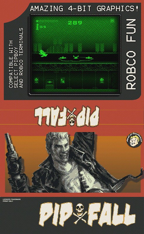
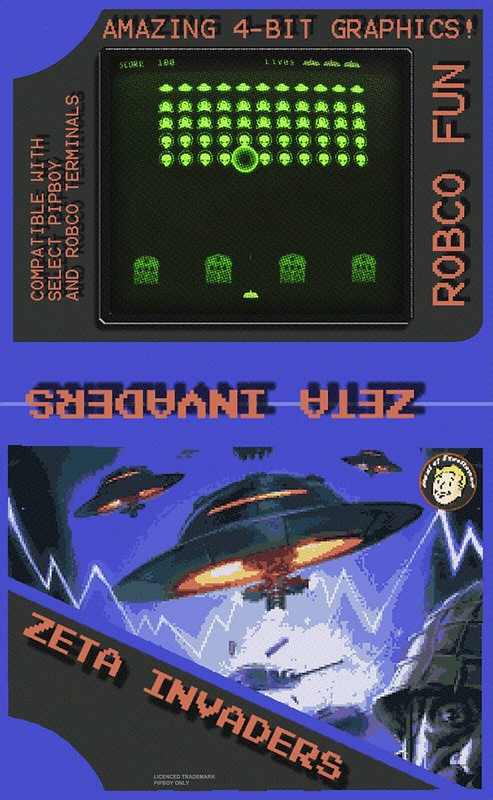
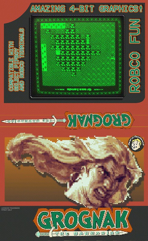
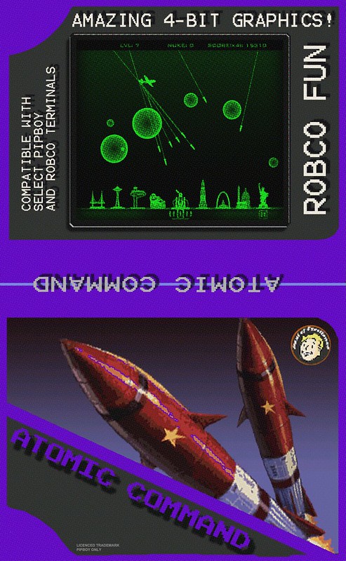
I got a bit carried away today with completing the Holotape design. For those who haven't played the game, there are five mini-games that come on Holotapes.
These effectively look like old video game cartridges. What I did was design a new piece to replace the orange component. This piece is 0.5mm thinner on three sides, in order to accept the application of an adhesive label.

Now if you want to build a game version of the Holotape, you just order the "Label ready" component. You can order it in white and dye it, or try and see if you want to use one of the shapeways pre-dyed colors.

------------------


I also designed artwork for each holotape. I extracted the in-game texture for each tape. The in-game texture didn't included a backside, so I made one up. Carefully matching the existing themes. I also applied a halftone effect over the whole thing to simulate a cheaply printed design.
Print the images at 49.6mm wide in order to scale correctly to the Holotape

Note, the middle text on each is flipped to keep in line with how the label looks in-game.

Collect all five!

------------------
 
[url]https://farm2.staticflickr.com/1607/25924626165_80d2dbfbfa_c.jpg[/URL]
(Rendering!)

I got a bit carried away today with completing the Holotape design. For those who haven't played the game, there are five mini-games that come on Holotapes.
These effectively look like old video game cartridges. What I did was design a new piece to replace the orange component. This piece is 0.5mm thinner on three sides, in order to accept the application of an adhesive label.

Now if you want to build a game version of the Holotape, you just order the "Label ready" component. You can order it in white and dye it, or try and see if you want to use one of the shapeways pre-dyed colors.

------------------

[url]https://farm2.staticflickr.com/1550/25898721976_d98894b231_c.jpg[/URL]

[url]https://farm2.staticflickr.com/1617/25624052230_12a7ee39cd_c.jpg[/URL]

[url]https://farm2.staticflickr.com/1586/25295919353_dd720bfa7f_c.jpg[/URL]

[url]https://farm2.staticflickr.com/1530/25291926094_72174833fe_c.jpg[/URL]

[url]https://farm2.staticflickr.com/1515/25898722646_bb037b7fd4_c.jpg[/URL]

I also designed artwork for each holotape. I extracted the in-game texture for each tape. The in-game texture didn't included a backside, so I made one up. Carefully matching the existing themes. I also applied a halftone effect over the whole thing to simulate a cheaply printed design.
Print the images at 49.6mm wide in order to scale correctly to the Holotape

Note, the middle text on each is flipped to keep in line with how the label looks in-game.

Collect all five!

------------------

Amazing work man! I'll definitely be using those game labels on mine, also btw for Automatron there will be a new holotape game coming out! Excellent work on the tapes sir :D
 

----
Hey everyone, first off please vote for my project by visiting the DragonBoard Contest page and clicking Vote.
----

No login is needed. You can vote once per day this week only, and each day they are giving out a DragonBoard 410c to the top projects. Now, onto why I am asking you to vote:


I have recently talked about why I decided to move away from the Udoo Neo. I was going back to the BeagleBone Black because it seemed to be the best supported product I could get. However, there are still some drawbacks to the BeagleBone Black. Namely I have to add on separate circuits for WIFI, Bluetooth, GPS, Audio Input/Output Speaker amp, and FM Radio.


Well a few weeks ago I came across the DragonBoard 410c from Qualcomm. It was announced a year ago and shipped in September. I have no idea how I didn't run across it in what I thought was an extensive search for capable single boards.


Here is the major feature list:
-1.2Ghz Quad Core Arm A53 processor (Much newer and faster than the single core 1Ghz A8 in the BBB)
-Supports Android 5.1, Debian Linux and Windows 10. It even comes with Android Pre-installed.
-Integrated WIFI, Bluetooth, GPS and FM radio. So that checks off almost everything I need at once.
-Built in Microphone with Analog audio Input/Output and Speaker amplifier.
-Doesn't use any exotic connectors that come from a single company in China (looking at you Udoo Neo)
-Slightly smaller than the BBB
-MISI DSI Video interface


This board seems like a no-brainer to use. Still, I came up with a list of the pro's and con's of switching from the BBB:
-The board is $75 versus $50. However there was far more than $25 of circuitry to add GPS, WIFI and Audio to the BBB, so that is a wash.
-It uses 1.8V logic, instead of the more common 3.3V logic. However level shifters for this are simple.
-It needs 8V to operate. So I will have to add a battery boost circuit. The BBB can run off of a 3V lithium ion battery, however to get USB and WIFI working I would have needed a 5V boost circuit. Also the Rad Meter gauge needs a 9V signal. So again, this is a wash.
-Finally, there is the MISI DSI Video interface. I had never heard of MISI DSI before. The 640x480 LCD I want to use I bought because it has a Parallel RGB interface, which is what the BBB also has. So the first thing I did was look for DSI to RGB converter chips. They exist, but are not readily available or well supported. I am currently in talks with the LCD manufacturer, as the control chip used on the LCD does support DSI, but it was wired for Parallel RGB. It also may be possible to wire the LCD using I2C.
 
Last edited:
Hey man B technician here. I just want to say that I've been absent from following your project because well you know how life gets. But now that I'm finally back on my feet and I see that you are still continuing this project I am more than excited and more than patient please take your time on this you're doing a great job I hope to be supporting this project very soon now that I've got a job that will allow me to do it. I know this might have been a while ago but I'm glad to see you and your wife are recovering well from surgery. Keep up the good work!
 
Hey folks!

Thanks for voting! Initially, I though I hadn't made it high enough to win, but today I got an email asking for my details. So it looks like I will be getting my hands on a DragonBoard 410c.

The DragonBoard is amazing. It has a processor faster then you will find in a Samsung Galaxy A5. It comes with ready to use builds of both Ubuntu Linux and Android. And they have full documentation ready to go. My only issue is figuring out how to convert the DSI video to Parallel RGB. If I can get a hold of the Toshiba convertor chip, then it should be a straightforward circuit. They used this chip in the Raspberry Pi LCD, but since I am not a 10k quantity customer, I will have to figure out how to get my hands on some of the chips. (I haven't been able to find a DSI display which is 4:3 aspect ratio and between 3.5" and 4" in size.)

5RS4myu.jpg


--------------------


The DragonBoard outside dimensions are not much different than the BeagleBone, where the big difference comes in is how thin it is.
The board only sits 7mm above the motherboard. This is half the height of the BeagleBone and Udoo. This allows me to orient the board sideways in the Pip-Boy, without hitting the arm band.

The BeagleBone board would have required soldering on a battery and USB connector due to the bad positions of those connectors. The DragonBoard will allow to connect a right angle USB cable without any modification to the board. All-in-all it is much more efficient and easier to integrate.

--------------------

I have been working hard on the project, and right now I have a bill of materials which includes all the hardware, but none of the custom electronics.
Currently the BOM total is $694.99. That does NOT include any shipping costs, and all the yet-to-be designed custom electronics. This is off-the-shelf and 3D printed parts only.
So my $700 to $1000 cost estimate still stands. I have done a lot to lower the total number of unique components. Early in the design there was over 30 unique pieces of hardware, now there are only 18. I am almost ready to order the whole BOM, except for the 3D printed components. That will wait until I have a working LCD screen on my desk.

Just as an example the Samsung Galaxy A5 price is $350, and I am pretty sure they will make a few million of those, so 2x or 3x the cost for a very low quantity custom build is that bad.

--------------------

At this point there are two items to solve before I can say the CAD design is done:
-Needle for rad gauge.
-DSI to Parallel RGB convertor chip.
 
J4xbu9O.png


So I may have found a cheap solution to my need for a high-resolution, 3.5", MIPI DSI LCD display. The iPhone 4S!
The iPhone 4 was one of the first phones to use a MIPI DSI LCD display. It is 3.5", 960x640 pixels, 3:2 aspect ratio (Close enough to 4:3), and has a 4-lane MIPI DSI interface.
In theory this is just what the DragonBoard requires.

This guy proved that the LCD screen can work with external video input. (He stopped development a year ago however)

The display, with attached glass is cheap on eBay. The catch is I want just the LCD. Most of the screens on eBay are sold with attached glass. The LCD is bonded to the glass using a UV adhesive, but the glass itself isn't actually required to use the LCD or touch-screen. I found plenty of "glass only replacement" videos on Youtube that demonstrate the screen works after the glass is removed. But I can't seem to find a source for just the raw LCD, without glass. You can find just the glass on eBay. As you can see above, the iPhone 4 is too large to fit with the glass attached.

My options are to buy a LCD and remove the glass (not easy), or to attempt to perhaps cut the glass using a diamond cutter. The funny part is there are shops selling jigs to help remove the glass adhesive.

For now, I will order the LCD, and related connectors. I will have to build a breakout board to find out if this crazy idea will work.
 

Your message may be considered spam for the following reasons:

If you wish to reply despite these issues, check the box below before replying.
Be aware that malicious compliance may result in more severe penalties.
Back
Top