Raveyote
You could print it in a metal material, however metal 3D printing would require lots of alternation and post-printing re-work. Metal 3D printing is done in one of two ways: Printed in a plastic/resin, then molded and cast. Or printed using a metal powder and binding agent, then put into a oven and baked. Both methods have shrinkage involved and are not very precise. The cost of 3D printed metal is also at 10x the cost of plastic. And the 3D printers for this materials can't print something as large as the Pip-Boy.
Many of the parts in the design could easily be cast after a 3D printed master was made, however these parts are also the cheapest to 3D print. They don't add much to the overall cost. The primary component is the front face, it has all the internal mounting holes and other features which can only be reliably created with a SLS 3D printer. There are mounting holes at 90 degree angles to the face, under-cuts and other features which make even flexible casting difficult. The primary issues is casting these parts can have issues with shrinkage, which makes the items like gears looser. The CAD model would have to be altered to adjust for the casting.
The Nylon material I am using is a material I have worked with quite a bit in the past. It is very strong, even at 2mm thick. It is solid, so you can sand or drill the surface without worrying about hitting a internal void. You can dye, or prime and paint the surface. You can polish it to a smooth mirror finish. The Nylon is also self-lubricating, which makes all the moving parts work together better. The parts come out very precise, and don't need any secondary machining to work as a gear or moving part. The most I have had to do is re-drill out a hole to make a pin fit in easier. I have even 3D printed built-in threads as small as M6 into a part and had a metal nut successfully thread onto it.
----------------
In regards to the cassette idea, I gotta say that is a great idea! But I have to think of the advantages/disadvantages.
I could easily find a small MicroSD card to USB adapter that could be wired up inside the holotape. The MicroSD card could protude a tiny bit out the back of the cassette so you can pull it out and update it. The MicroSD card could then actually hold the audio/video file that is to be played back. Or a text file could be read and trigger an action on the Beaglebone. It makes the holotapes less fake, but it may also be overkill, since you won't be finding any of these in the real world, or swapping them with a fellow Pip-Boy owner.
Here are the complications:
There is only one USB jack on the Beaglebone. I plan on using that for WIFI, just because the modules are inexpensive and android ready. Adding a non-USB WIFI module is possible, but far more complicated. Even with the single USB port, I don't have physical room for even the tiny USB WIFI modules, so the USB jack will have to be de-soldered, and a header put in its place just to wire in the WIFI.
Adding a 2nd USB port requires a USB hub. Yes, hubs are cheap. However even an off-the-shelf hub simply won't fit, no matter how small. A USB hub integrated circuit that I put onto the motherboard is possible, but also adds cost and is power hungry. Remember when running on a battery I only have 3.7V (at full charge) available. USB typically requires 5V. I have seen some people who have gotten USB devices to run off 3.3V, but it really depends on the connected device.
In the end I have to balance out what features make the Pip-Boy functional as a game interface, versus what functions would make it more like a real-life Pip-Boy. Originally I had aspirations to add all sorts of sensors to the Pip-Boy.
Here is the original list of ideas which me and my friend came up with, and why they were rejected.
Sensors:
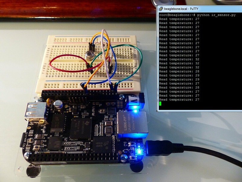
-Skin temperature
How: IR sensor pointed towards arm.
Reason rejected:: IR sensors cost $15, or require a tiny expensive to solder BGA chip. Padding may block signal.
-Relative humidity (Weather sensor)
How: Sensor IC. (~$3)
Reason rejected: Board space, and requires a custom made app.
-Barometric pressure (Weather sensor)
How: Sensor IC (~$7)
Reason rejected: Board space, and requires a custom made app.
-Accelerometer (Detect a hit to the player.)
How: Sensor ID (~$3)
Reason rejected: Board space, and requires a custom made app.
-Magnetometer (Digital compass)
How: Sensor ID (~$3)
Reason rejected: I may add this in if the Android native GPS apps can read the data, otherwise same issues as above.
-Heartrate monitor (Player health)
How: Green LED and light sensor wrapped around player's wrist.
Reason rejected: This method is how the low-cost finger heartrate sensors work at a hospital. But for it to work on your wrist you need custom processing. Watch companies barely got this work this year using a custom made sensor and processor. It is out of my reach for this project.
-Full-size Geiger counter
How: Copy the spark-fun geiger counter circuit. ($110)
Reason rejected: 500V a few millimeters from your arm. Expensive. Takes up a huge amount of board space. Pin-Diode detector is low-cost and is still a real Gamma ray detector. Even with the Pin-Diode detector, you need to put a radioactive sample within an inch to even detect Gamma rays, so it's really on staying in the Pip-Boy for bragging rights.
-Air quality sensor:
How: Multiple sensor chips ($15)
Reason rejected: Expensive, requires custom app.
At $1000 (current estimate), the Pip-Boy is already very expensive to build. There are three primary uses for this replica prop:
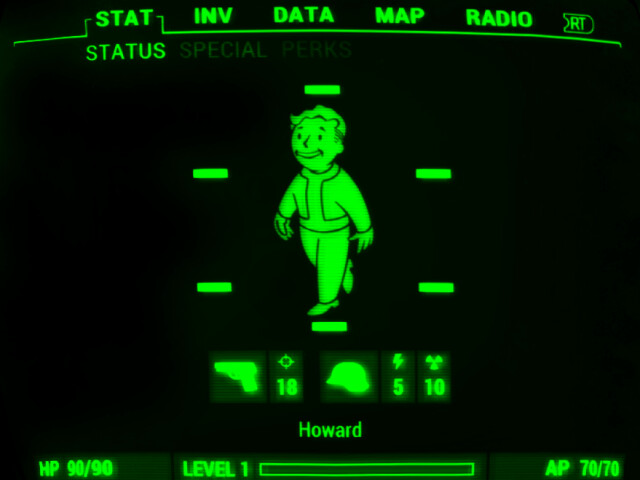
1) Bragging rights. And being able to say "Yes, it really works. Yes, it can detect Gamma radiation, Yes, every knob works."
2) In-Game. Increasing the immersive effect of the game. Being able to use the companion app and Pip-Boy to cause an effect in-game. Even this may require a custom app to alter the behavior of the companion app. (For example if the companion app doesn't have any keyboard input)
3) During cos-play. Being able to pull up your Pip-Boy and pull up a map or your surroundings and navigate like you do in game. Putting in a holotape and hearing an audio log play. Both of these also require custom apps.
Adding even more to the design would be cool for #1, but I think its already complex enough to impress any Fallout fan or geek.


")