Aces
New Member
@ jellis359
I still don't think that having both the bearings and the planetary gears would fit in the space we have to work with. The problem I have it that the 9/16" rod is required, since that is the inner diameter of my driving gears that I pulled from the hand drill. I'd say our best bet would either be
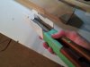
1. the diagram I sent you with the rod catches
2. the modified version you replied with
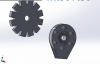
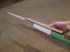
3. if we want to have them go in the same direction and can deal with the slowing turning due to the gear rations, this is what I mentioned earlier:

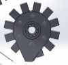
This was just a quick sketch, and of course the teeth would need to line up, but if we can have the catches on the inside of the sun gear, and build the rest of the capped "gear" around the outside, it could produce esentially everything we need. Delayed start, clockwise rotation, and a slight spin off with the rod catches.
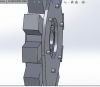
With either herringbone gears or a piece to hold the planets in place, which would be attached to the stock, we could hold everything in place.
If that's not feasible, I think I will go with all counter clockwise rotation, and rod catches.
In either case, could you send me the modified capped gear when you are done, with just a 9/16" center hole? I don't get access to solidworks through my university unless I can prove that I'm taking a course that requires it, so that it off the table unfortunately.
I still don't think that having both the bearings and the planetary gears would fit in the space we have to work with. The problem I have it that the 9/16" rod is required, since that is the inner diameter of my driving gears that I pulled from the hand drill. I'd say our best bet would either be
1. the diagram I sent you with the rod catches
2. the modified version you replied with
3. if we want to have them go in the same direction and can deal with the slowing turning due to the gear rations, this is what I mentioned earlier:
This was just a quick sketch, and of course the teeth would need to line up, but if we can have the catches on the inside of the sun gear, and build the rest of the capped "gear" around the outside, it could produce esentially everything we need. Delayed start, clockwise rotation, and a slight spin off with the rod catches.
With either herringbone gears or a piece to hold the planets in place, which would be attached to the stock, we could hold everything in place.
If that's not feasible, I think I will go with all counter clockwise rotation, and rod catches.
In either case, could you send me the modified capped gear when you are done, with just a 9/16" center hole? I don't get access to solidworks through my university unless I can prove that I'm taking a course that requires it, so that it off the table unfortunately.