You are using an out of date browser. It may not display this or other websites correctly.
You should upgrade or use an alternative browser.
You should upgrade or use an alternative browser.
Energizer Lightsaber project - as originally made
- Thread starter thd9791
- Start date
Benjo
Active Member
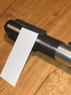
Awesome !I’m restarting this too. This time I nabbed a 19” maglite… spun it in my drill press and sanded it down!
Now there’s no button hole, and there was only knurling on the upper 3rd, but I wanted it all the same diameter
View attachment 1668747View attachment 1668748View attachment 1668753
I spun a core and set it with a button head screw like the original… and I took some third and fourth glances to the structure visible in my cast.
View attachment 1668749View attachment 1668750View attachment 1668751View attachment 1668752
After searching through the plastruct and evergreen catalogue, there are no straight parts that will work. Instead I took thick sheet and sculpted it with a heat gun!! Seriously, my first time… some of it deformed a little too much, but I’m proud to say it worked. I calculated circumference for the two strips/layers I see in the cast, one is longer than the other. Then I filled the voids with resin to start off
View attachment 1668755View attachment 1668756View attachment 1668758View attachment 1668759View attachment 1668760View attachment 1668761View attachment 1668762View attachment 1668763View attachment 1668764View attachment 1668765
Did you choose to keep the exact same dimensions and lenght as the resin cast ?
To a degree. So it seems, if I’m looking at the maglite endcap, there is a little shrinkage. So for most of the big details I’m going a tad larger.. eyeballing everything so it’s probably between 1-3mm … also if I **** up I can still remove material and stay in range hahaAwesome !
Did you choose to keep the exact same dimensions and lenght as the resin cast ?
I’m also only working with what I can get my hands on physically rather than hunting part numbers. This styrene sheet I used for the collar is a hair thinner probably.
Okay, so I decided to attempt to recreate the control box.
The one on the prop just looks like a cake. I wouldn’t be surprised if this was putty or bondo surrounding a frame.
I’m looking at the thicknesses of styrene I have on hand, I couldn’t make the box out of two interlocking parts like I wanted. Instead, I made a thin frame and filled it with resin. Yes it spilled the first time!


I also built up the other parts in the same model maker way. There was no way I was going to get straight lines this way, but I’m trying to duplicate the type of model making to get a similar looking result and explore the build process.

So, this was a messy process but I managed to pull it off. The rails… they are angled strip on the real prop and I think I could re-do them. I’ll just sand them off and make new ones… I was going to lay a new piece of styrene over the screws anyways.
I have a new detail about the control box, -and some new details about the filming process. going to check and see if I can share.
There appears to be room for the vinyl sheet under the control box, I think that happened because the tapping in the tube is 3/4 turn off of the box.


I have Delrin coming soon…
The one on the prop just looks like a cake. I wouldn’t be surprised if this was putty or bondo surrounding a frame.
I’m looking at the thicknesses of styrene I have on hand, I couldn’t make the box out of two interlocking parts like I wanted. Instead, I made a thin frame and filled it with resin. Yes it spilled the first time!
I also built up the other parts in the same model maker way. There was no way I was going to get straight lines this way, but I’m trying to duplicate the type of model making to get a similar looking result and explore the build process.
So, this was a messy process but I managed to pull it off. The rails… they are angled strip on the real prop and I think I could re-do them. I’ll just sand them off and make new ones… I was going to lay a new piece of styrene over the screws anyways.
I have a new detail about the control box, -and some new details about the filming process. going to check and see if I can share.
There appears to be room for the vinyl sheet under the control box, I think that happened because the tapping in the tube is 3/4 turn off of the box.
I have Delrin coming soon…
Soooo… I am following the project as Adam Savage says.
The control box just wasn’t working. It looked wrong and all my adjustments made it worse so I started from scratch and made a new box. Same process, welding a styrene box and filling it with resin.


Um, and I also blanked the holes I drilled earlier, for good practice

Milliput saved the day and I was able to sculpt the shroud into a better shape. Wait overnight. Idk why but it was harder the next day as opposed to the 4 hour mark or whatever they say.


The other neat thing is that I found material the right thickness and profile of the Energizer bunny track. This is Plastruct I beam. I sliced it up and shaped the 7 t track from it. The back is beveled. 3 are shorter and 4 are longer. At least one has the beveled end trimmed short leaving the flat part of the track. I tried to mimic them the best I could. I used e-6000 so I can easily drill the screws for the grips without fumbling placement.


The control box just wasn’t working. It looked wrong and all my adjustments made it worse so I started from scratch and made a new box. Same process, welding a styrene box and filling it with resin.
Um, and I also blanked the holes I drilled earlier, for good practice
Milliput saved the day and I was able to sculpt the shroud into a better shape. Wait overnight. Idk why but it was harder the next day as opposed to the 4 hour mark or whatever they say.
The other neat thing is that I found material the right thickness and profile of the Energizer bunny track. This is Plastruct I beam. I sliced it up and shaped the 7 t track from it. The back is beveled. 3 are shorter and 4 are longer. At least one has the beveled end trimmed short leaving the flat part of the track. I tried to mimic them the best I could. I used e-6000 so I can easily drill the screws for the grips without fumbling placement.
Thank you!
Here is my next scratchbuild update. I happened to have some of that crappy press-on silicone putty right? Well I made a bucket that could reproduce the box I scratch made. Worked out decently well, but my original was too wide! So I cut the cast down and puttied the bottom to make it taller. I can mold THIS for people if they want, I’m going to have extra shrouds when I mold that
Anyway, I also decided to make the top a separate thing. I kept screwing up trying to duplicate the rails, and just took a relief cast. I embedded magnets to hold it on so I can access the screws to put on the clamp material.


The relief cast of the top of the control box is destroyed. I only wanted to use one for my own build and I will not sell it. You’ll have to make that part yourself")
The shroud has some more putty in the corners to make it really sharp. I’ll eventually mold that.. I think they did it upside down, I can just make a clay ridge that can be cut off to bring the whole emitter bottom up to one level, right?
Here is my next scratchbuild update. I happened to have some of that crappy press-on silicone putty right? Well I made a bucket that could reproduce the box I scratch made. Worked out decently well, but my original was too wide! So I cut the cast down and puttied the bottom to make it taller. I can mold THIS for people if they want, I’m going to have extra shrouds when I mold that
Anyway, I also decided to make the top a separate thing. I kept screwing up trying to duplicate the rails, and just took a relief cast. I embedded magnets to hold it on so I can access the screws to put on the clamp material.
The relief cast of the top of the control box is destroyed. I only wanted to use one for my own build and I will not sell it. You’ll have to make that part yourself
The shroud has some more putty in the corners to make it really sharp. I’ll eventually mold that.. I think they did it upside down, I can just make a clay ridge that can be cut off to bring the whole emitter bottom up to one level, right?
this update contains a few things.
1) I have black resin and new silicone in the mail. Dumb Tom drilled and installed magnets in something I’m going to cast, so that was totally unnecessary.. but it did work as a prototype, seeing if the theory could work.
I’m going to cast the shroud upside down and the box sideways. I may cast the grips but I don’t think I will. The plastruct material is much stronger than a resin piece would be.
2) the shroud is thinner now. I will add pictures later… I hilariously worked in such a high standard I made the box part of the shroud the exact same height as the greeblie and D ring block.
They’re not. It’s lower, and it’s exactly the same on the barbican. Nice job duplicating the original prop Don lol
(I made a D ring block out of half inch aluminum bar, just like the Barbican. It appears the original energizer saber used two pieces of styrene sandwiching a ring in between them. I may cast the block as part of the emitter or I may not… I like the idea of the ring being supported by metal screwed to the resin, instead of 2mm of resin
I found that 6/32 button head screws seem to match the ones on the original. They could be a metric equivalent, we’re really just matching the size of the screw heads
0-80 button head screws are a little too small for the ones on the grips, I have to search for better ones
I also have… DRUMROLL…. A theory for the grip material.
I have searched high a low through vinyl sheet, ribbed tape, textured or embossed tape, etc and couldn’t find anything in the model making stores. LOM suggested some of the textured sheet and I was like oh! I used flat sheet to make the round shroud, why not the center?
This is .060 corrugated siding, which is not actually metal but styrene. The original prop has pretty sharp ridges, and the casts are a little rounded or squashed. I think this is from repeated molding and the original might be like this.. from the heat needed to bend the plastic.
Behold.

The ridges are spaced at 1.5mm and that’s what my calipers read when I measure valley to valley on the cast. They’re .02mm larger than the cast which kinda makes sense
The back is flat too
I’m going to cut some and heat wrap it and see what happens. I’ll also capture the new shroud shape
1) I have black resin and new silicone in the mail. Dumb Tom drilled and installed magnets in something I’m going to cast, so that was totally unnecessary.. but it did work as a prototype, seeing if the theory could work.
I’m going to cast the shroud upside down and the box sideways. I may cast the grips but I don’t think I will. The plastruct material is much stronger than a resin piece would be.
2) the shroud is thinner now. I will add pictures later… I hilariously worked in such a high standard I made the box part of the shroud the exact same height as the greeblie and D ring block.
They’re not. It’s lower, and it’s exactly the same on the barbican. Nice job duplicating the original prop Don lol
(I made a D ring block out of half inch aluminum bar, just like the Barbican. It appears the original energizer saber used two pieces of styrene sandwiching a ring in between them. I may cast the block as part of the emitter or I may not… I like the idea of the ring being supported by metal screwed to the resin, instead of 2mm of resin
I found that 6/32 button head screws seem to match the ones on the original. They could be a metric equivalent, we’re really just matching the size of the screw heads
0-80 button head screws are a little too small for the ones on the grips, I have to search for better ones
I also have… DRUMROLL…. A theory for the grip material.
I have searched high a low through vinyl sheet, ribbed tape, textured or embossed tape, etc and couldn’t find anything in the model making stores. LOM suggested some of the textured sheet and I was like oh! I used flat sheet to make the round shroud, why not the center?
This is .060 corrugated siding, which is not actually metal but styrene. The original prop has pretty sharp ridges, and the casts are a little rounded or squashed. I think this is from repeated molding and the original might be like this.. from the heat needed to bend the plastic.
Behold.
The ridges are spaced at 1.5mm and that’s what my calipers read when I measure valley to valley on the cast. They’re .02mm larger than the cast which kinda makes sense
The back is flat too
I’m going to cut some and heat wrap it and see what happens. I’ll also capture the new shroud shape
I am reporting back. I did it. I will start with how Styrene seems to react (anecdotal story)
I have a Black and Decker heat gun, I got it at an estate sale or something, it is basic and has two settings: somewhere around 500F and over 1000F. On the first setting this styrene (see thickness below) takes a long time to bend. Long enough for your thoughts to stray and then all of a sudden its wrinkling like slightly melting sheet frosting. On the highest setting this happens very quickly. There is a sweet spot for each plastic part and i recommend keeping the plastic moving, and pressing on it a little so you know the EXACT time its pliable. You can also reheat wrinkled areas and reshape them... gently. For both the shroud and this new part, I used an aluminum tube the diameter i want, and the maglite itself, as a backer to form the mold. I wore buffalo hide gloves, do not do this without gloves. I also held the styrene at least a few inches away from the gun.
Here is the new material. I used painters tape to measure the circumference of the cast - this would be the length, and held it up against the cast to get the height. Then regretted it because the cast is smaller. I've heard the large details shrink more than small details. so my initial pieces were too short, the body of a real maglite is thicker.


thankfully I had enough to re-do it. These are too short but it gives you an idea

After heating and a dusting of rustoleum gray automotive primer and professional flat black, just because they are all i had on hand..


and I did make a D-ring block. Dremel and hacksaw.... and proper tapping of 6-32 screws. I'm going to install the D ring after I decide what to do with casting..

and of course... I cut down the shroud back face so its lower than the greeblies! I welded and CA glued a new piece of styrene over it so it would be flat in the mold.

I'm going to include the low-res images we have of the original.


and resin copies


I have a Black and Decker heat gun, I got it at an estate sale or something, it is basic and has two settings: somewhere around 500F and over 1000F. On the first setting this styrene (see thickness below) takes a long time to bend. Long enough for your thoughts to stray and then all of a sudden its wrinkling like slightly melting sheet frosting. On the highest setting this happens very quickly. There is a sweet spot for each plastic part and i recommend keeping the plastic moving, and pressing on it a little so you know the EXACT time its pliable. You can also reheat wrinkled areas and reshape them... gently. For both the shroud and this new part, I used an aluminum tube the diameter i want, and the maglite itself, as a backer to form the mold. I wore buffalo hide gloves, do not do this without gloves. I also held the styrene at least a few inches away from the gun.
Here is the new material. I used painters tape to measure the circumference of the cast - this would be the length, and held it up against the cast to get the height. Then regretted it because the cast is smaller. I've heard the large details shrink more than small details. so my initial pieces were too short, the body of a real maglite is thicker.
thankfully I had enough to re-do it. These are too short but it gives you an idea
After heating and a dusting of rustoleum gray automotive primer and professional flat black, just because they are all i had on hand..
and I did make a D-ring block. Dremel and hacksaw.... and proper tapping of 6-32 screws. I'm going to install the D ring after I decide what to do with casting..
and of course... I cut down the shroud back face so its lower than the greeblies! I welded and CA glued a new piece of styrene over it so it would be flat in the mold.
I'm going to include the low-res images we have of the original.
and resin copies
Attachments
Benjo
Active Member
Very interesting. We already talked about that shrinkage/Maglite body diameter problem by the past, the ILM cast seems way too small compare to the real maglite but, your last pictures pushed me to compare your versions to other casts of this prop and it seems you've done it right. Yours looks closer to the resin hilt on the Lucasfilm archives, apparently a bit fatter than the ILM cast.
Very good idea to use styrene ribbed sheet for the middle band. I remain sure Don Bies used ribbed kitchen sheet though but your idea looks damn right.
Very good idea to use styrene ribbed sheet for the middle band. I remain sure Don Bies used ribbed kitchen sheet though but your idea looks damn right.
I'm getting ready for an Apt this morning but wanted to reply, and thank you. You're right, the lucasfilm casts seem a bit more beefy, like mine, and the way I've been doing this...Very interesting. We already talked about that shrinkage/Maglite body diameter problem by the past, the ILM cast seems way too small compare to the real maglite but, your last pictures pushed me to compare your versions to other casts of this prop and it seems you've done it right. Yours looks closer to the resin hilt on the Lucasfilm archives, apparently a bit fatter than the ILM cast.
Very good idea to use styrene ribbed sheet for the middle band. I remain sure Don Bies used ribbed kitchen sheet though but your idea looks damn right.
basically I look at the cast and judge the details based on what it would have looked like at full size. extrapolate it all out. If something is wrinkly, I check if it's from the casting process or a detail on the hilt itself. Hard to tell sometimes, but I've been able to gather good conclusions based on other casts we have to deal with in this hobby.
I have talked to Don a little bit - the center band he doesn't remember (but he knows its not vinyl/rubber sheet) and his best guess was sheet aluminum run through an embossing machine ILM had. I think this is hilariously on point. Anyway, the whole corrugated styrene route is perfectly good imo, especially for our needs, and this looks EXACTLY like the mid band on the DV6. Like the material. That still could be metal, but I see warping and aging that looks a lot like this styrene sheet when it deforms. Smooth, obviously, but same idea.
Alright, I’ve slowly got materials showing up on my doorstep. I jumped at the chance to mold my scratch made box, and make it in black resin. I re-did the magnet thing properly in the final version. Sanding those two control box pieces flat was really hard for some reason. Also, I did this with a hand drill and nothing lined up haha. Holes were crooked and I had to drift the holes in the box to get it to line up perpendicular. That’s all internal so I think I’ve got it pretty good. Granted, it’s a little uneven and the band sits a little high.
I used E6000 on the magnets, and I hope it stays. One drop underneath and a little on top, smeared and cleaned off. I’m going to wait 24 hours so it has the maximum bond and hopefully will overcome the attraction of the magnets.
I have TS black spray paint coming for the midband and black parts. I may brush some on the grips too, this is gray automotive primer on the midband… flat black grips and I’m unsure about them.


I next have to mold the emitter. I did it once already and royally ****** up. It has to be a 2 piece mold, the flange inside and outside both prevent you from drawing it out in either direction. And you can get the inside if you do it sideways. I’m going to mold it in 2 parts with a seam line at the flange.
I used E6000 on the magnets, and I hope it stays. One drop underneath and a little on top, smeared and cleaned off. I’m going to wait 24 hours so it has the maximum bond and hopefully will overcome the attraction of the magnets.
I have TS black spray paint coming for the midband and black parts. I may brush some on the grips too, this is gray automotive primer on the midband… flat black grips and I’m unsure about them.
I next have to mold the emitter. I did it once already and royally ****** up. It has to be a 2 piece mold, the flange inside and outside both prevent you from drawing it out in either direction. And you can get the inside if you do it sideways. I’m going to mold it in 2 parts with a seam line at the flange.
Okay folks. I am proud to say I successfully made another 2 part mold. Here is me pulling it apart,
I'm sorry for the flash, I didn't edit this
Anyway, I made some air vents and a couple pour spouts to make sure as many bubbles get out as possible if I slosh it around. I'll have to dremel the final casts a little bit but no worries.


And once opened up....


Yeah, I ordered two completely different silicone hardnesses by accident so I guess they're also color coded. The purple is less flexible.
Now, to top this all off, I found some M2.5 button head screws that seem to match the original. Though, we know the original had pointy sheet metal or wood screws... I happen to have a good M2.5 tap set here


Thats how the box looks (6-32 socket head bolts) when the magnetic cap is set in place.
I'm sorry for the flash, I didn't edit this
Anyway, I made some air vents and a couple pour spouts to make sure as many bubbles get out as possible if I slosh it around. I'll have to dremel the final casts a little bit but no worries.
And once opened up....
Yeah, I ordered two completely different silicone hardnesses by accident so I guess they're also color coded. The purple is less flexible.
Now, to top this all off, I found some M2.5 button head screws that seem to match the original. Though, we know the original had pointy sheet metal or wood screws... I happen to have a good M2.5 tap set here
Thats how the box looks (6-32 socket head bolts) when the magnetic cap is set in place.
At this point in the project, I wanted to survey the community
Interest - Energizer kit - interest survey
There are ways to use a pipe.... I could mold the endcap with a 1-3/8 stem for example, anyway, I'm painting up my shroud today!
Interest - Energizer kit - interest survey
There are ways to use a pipe.... I could mold the endcap with a 1-3/8 stem for example, anyway, I'm painting up my shroud today!
I don’t have pictures of this but I took a huge forstner bit, one that was almost as wide as the flashlight and pushed gently into the inside step, spiraling it around so I bored the same amount all the way around!
It worked.


Now the shroud sits lower.
I also rubbed some acrylic lacquer on the D ring block, and installed one of my own. Very gently as to not crack the resin.

I dusted the painted parts with some good ol Tamiya TS matte clear. Looks wonderful…


It worked.
Now the shroud sits lower.
I also rubbed some acrylic lacquer on the D ring block, and installed one of my own. Very gently as to not crack the resin.
I dusted the painted parts with some good ol Tamiya TS matte clear. Looks wonderful…
Similar threads
- Replies
- 6
- Views
- 568
- Replies
- 2
- Views
- 266
- Replies
- 0
- Views
- 465