TerranCmdr
Well-Known Member
Hello!
I shot a lot of video of the building of this and will be editing it together, but I wanted to post a build log to show it off just because I'm really happy with it.
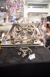
So this is Doc Brown's Brain Wave Analyzer, as seen in BTTF when Marty first meets past-doc. (This is an image of the original prop, it's not in the greatest shape)

And here's a shot of the finished prop. I'm really happy with it. (and yes, it lights up!)

I still have a couple of finishing touches to put on, and there are a couple of inaccuracies that I will explain in the build process.
So, my buddy really wanted this helmet for Halloween and I decided to dive in, having little knowledge of working with metal, foam, or electronics. First step was to get it modeled in 3D, I used Rhino as I had planned to export the supports as outlines that I could print and use for actual templates. This was the first time I realized this was going to be much more work than I initially thought, as I realized there were actually 8 different sizes for the supports. I did the export and used the templates to create a cardboard mockup, to see if it would all work, and it looked pretty good!


So I pressed onward. I went back to my 3d model and searched TAP Plastics for sizes of acrylic that were close to what I needed, and adjusted the model accordingly. I ended up with 1.5"OD acrylic tube and 0.625" acrylic rod. The people at TAP were super helpful as always and set me up with some glue and an acrylic drill bit as I also planned to add a cap on the acrylic tubes (I later scrapped this idea). I printed out a breakdown of the posts (of which there are 13) for me to follow.


Before I got to work on the acrylic I decided to create the inner soft helmet. I picked up foam floor mats from Harbor Freight and used some Barge glue to assemble. This was my first time working with foam like this and the pieces started to separate after a day or so, not sure if I waited too long to stick them together or not long enough (I waited 12 minutes after application.) At this time I also decided to do a quick mockup of the LED circuit I'd need to create. I found a circuit planner online and decided to do 4 parallel circuits, 3 of 4 LEDs and 1 of 1, with the proper resistors. After wiring it up it seemed to work great! I used amber LEDs to simulate the original incandescent bulbs of the prop.


So, after stopping by my Uncle's house to borrow his chop saw, I got to work on the acrylic. I was thinking I would have to buy a new blade for the acrylic but I decided to do a test cut and it looked fine, so I went ahead and cut all 13 sections of tube and acrylic. I then got to work on the metal tubes. I searched (maybe not hard enough) for a thin metal cylinder that was 2" diameter but to no avail. So I cut flat metal strips out of thin aluminum and, using an acrylic tube as a tool, rolled 13 strips into 13 cylinders and fastened them with rivets. I also assembled the first iteration of the metal cap at this point, also with sheet metal and rivets. Additionally you can see my test 3d print of a washer. These go on top of the wood rounds that connect the posts to the helmet. I decided to go 3d printed to save weight and money as I was afraid this thing was going to be super heavy. I ended up spraying them with filler primer and using rub-n-buff for a metallic finish.


The next thing I needed to figure out was the wood rounds that form the base of the posts. To keep everything in proportion with the acrylic the wood rounds needed to be 1.75" diameter. Not a super common size but I was able to find a dowel at a local(ish) woodworking store. It was walnut I think and it was by far the nicest wood I've ever worked with.
(Side note - my initial plan was to use hole saws to cut these rounds, but unfortunately I didn't realize that hole saw sizes describe the outer diameter, not the inner. So the 1.75" hole saw I picked up actually cut a roughly 1.5" round.)
After chopping the wood rounds to size It only took me about 5 minutes to realize drilling the 3 holes in each by hand was not going to work. Not only did they need to be perfectly perpendicular but it would just take way too long to do it all with a hand drill. So I bit the bullet and bought a cheap drill press from Harbor Freight. No regrets, I love it and will get a lot of use out of it. I also used the drill press to put holes in the acrylic and the metal cylinders. Each rod needed a hole at the end for the LED and a hole through the middle for assembly. Cylinders also needed 2 throughholes. I actually 3d printed a jig for the metal cylinders so I could hold them in place and drill them without squishing them.


I used 1/4" hardware and 3d printed spacers to assemble the posts. Shown below is my imperfect test piece. I went ahead and began drilling holes in the metal frame to attach the posts (they go on with 2x 1/4" round head slot screws) and at that point realized that I would have to remake that metal cap. What happens is when the wood pieces are tightened to the metal cap, they draw it flat against the wood and therefore change the dimensions of the cap. I used my first metal cap as a guide for the second one, measuring and comparing after each attachment point. This is when I really thanked myself for getting that drill press because all the acrylic rods press-fit beautifully into the wood.


The next step would be the final "big" thing to do and also the most challenging. After installing the posts I knew I could never use the standardized support sizes and would have to measure each span individually. So that's what I did, I took two measurements for each span and hand-drew a template for each one. I measured, created a template, traced, cut out of sheet metal, and assembled with rivets. I didn't want to measure all the spans at once because I knew the span sizes would change as I assembled. In all I ended up drawing 17 templates. Some spans just ended up being the same, and for the secondary and tertiary spans (the 4 lateral uppers and the 8 diagonals) I was able to average the distance and use one or two sizes (well, more like 6 for the diagonals).


About halfway into doing the spans I realized I should have wrapped the armature wire around the wood first, as the spans made it pretty difficult to get to the posts. The last step was to add LEDs, and I was on a very tight timeline at this point as my friend asked if I could get it done 2 days early for a costume contest. So I got to work getting the LEDs glued in with hot glue and wired up using an assortment of wires I purchased and had on hand. Each connection was soldered and sealed with heat shrink and to my honest surprise, everything lit up on the first try! The finishing touches were to wrap the thin red wires around the bases of the acrylic tubes (my wife stepped in to help as we had literally hours left) and install the wire clamps. This is something that bothered me with the inaccuracy. The wire clamps used on the original prop are metal with white sides, but the only ones I could find were metal with black sides. Not a detail most people would care about but I wanted this to be as accurate as possible. Maybe in the future I can find the right ones and upgrade the helmet. Another frustrating thing that happened here was that the rivets I was trying to use to attach the clamps were just not working. They had to be large enough for the hole in the wire clamp but the cheap hand-riveter just couldn't deal with them. So I used screws and nuts from my junk drawer to get the clamps on, I figured that was pretty fitting for the helmet anyway.


And that's about it! My friend picked it up and loved it, and it was a huge hit at the event he wore it to. I still plan to add a belt chin strap to this, as well as the black cross-shaped wires at the end of each LED to really finish off the entire thing. We are also planning to create the suction cup that Doc sticks on Marty's forehead for some great interaction possibility (when the state of the world permits). Thanks for looking!


I shot a lot of video of the building of this and will be editing it together, but I wanted to post a build log to show it off just because I'm really happy with it.
So this is Doc Brown's Brain Wave Analyzer, as seen in BTTF when Marty first meets past-doc. (This is an image of the original prop, it's not in the greatest shape)
And here's a shot of the finished prop. I'm really happy with it. (and yes, it lights up!)
I still have a couple of finishing touches to put on, and there are a couple of inaccuracies that I will explain in the build process.
So, my buddy really wanted this helmet for Halloween and I decided to dive in, having little knowledge of working with metal, foam, or electronics. First step was to get it modeled in 3D, I used Rhino as I had planned to export the supports as outlines that I could print and use for actual templates. This was the first time I realized this was going to be much more work than I initially thought, as I realized there were actually 8 different sizes for the supports. I did the export and used the templates to create a cardboard mockup, to see if it would all work, and it looked pretty good!
So I pressed onward. I went back to my 3d model and searched TAP Plastics for sizes of acrylic that were close to what I needed, and adjusted the model accordingly. I ended up with 1.5"OD acrylic tube and 0.625" acrylic rod. The people at TAP were super helpful as always and set me up with some glue and an acrylic drill bit as I also planned to add a cap on the acrylic tubes (I later scrapped this idea). I printed out a breakdown of the posts (of which there are 13) for me to follow.
Before I got to work on the acrylic I decided to create the inner soft helmet. I picked up foam floor mats from Harbor Freight and used some Barge glue to assemble. This was my first time working with foam like this and the pieces started to separate after a day or so, not sure if I waited too long to stick them together or not long enough (I waited 12 minutes after application.) At this time I also decided to do a quick mockup of the LED circuit I'd need to create. I found a circuit planner online and decided to do 4 parallel circuits, 3 of 4 LEDs and 1 of 1, with the proper resistors. After wiring it up it seemed to work great! I used amber LEDs to simulate the original incandescent bulbs of the prop.
So, after stopping by my Uncle's house to borrow his chop saw, I got to work on the acrylic. I was thinking I would have to buy a new blade for the acrylic but I decided to do a test cut and it looked fine, so I went ahead and cut all 13 sections of tube and acrylic. I then got to work on the metal tubes. I searched (maybe not hard enough) for a thin metal cylinder that was 2" diameter but to no avail. So I cut flat metal strips out of thin aluminum and, using an acrylic tube as a tool, rolled 13 strips into 13 cylinders and fastened them with rivets. I also assembled the first iteration of the metal cap at this point, also with sheet metal and rivets. Additionally you can see my test 3d print of a washer. These go on top of the wood rounds that connect the posts to the helmet. I decided to go 3d printed to save weight and money as I was afraid this thing was going to be super heavy. I ended up spraying them with filler primer and using rub-n-buff for a metallic finish.
The next thing I needed to figure out was the wood rounds that form the base of the posts. To keep everything in proportion with the acrylic the wood rounds needed to be 1.75" diameter. Not a super common size but I was able to find a dowel at a local(ish) woodworking store. It was walnut I think and it was by far the nicest wood I've ever worked with.
(Side note - my initial plan was to use hole saws to cut these rounds, but unfortunately I didn't realize that hole saw sizes describe the outer diameter, not the inner. So the 1.75" hole saw I picked up actually cut a roughly 1.5" round.)
After chopping the wood rounds to size It only took me about 5 minutes to realize drilling the 3 holes in each by hand was not going to work. Not only did they need to be perfectly perpendicular but it would just take way too long to do it all with a hand drill. So I bit the bullet and bought a cheap drill press from Harbor Freight. No regrets, I love it and will get a lot of use out of it. I also used the drill press to put holes in the acrylic and the metal cylinders. Each rod needed a hole at the end for the LED and a hole through the middle for assembly. Cylinders also needed 2 throughholes. I actually 3d printed a jig for the metal cylinders so I could hold them in place and drill them without squishing them.
I used 1/4" hardware and 3d printed spacers to assemble the posts. Shown below is my imperfect test piece. I went ahead and began drilling holes in the metal frame to attach the posts (they go on with 2x 1/4" round head slot screws) and at that point realized that I would have to remake that metal cap. What happens is when the wood pieces are tightened to the metal cap, they draw it flat against the wood and therefore change the dimensions of the cap. I used my first metal cap as a guide for the second one, measuring and comparing after each attachment point. This is when I really thanked myself for getting that drill press because all the acrylic rods press-fit beautifully into the wood.
The next step would be the final "big" thing to do and also the most challenging. After installing the posts I knew I could never use the standardized support sizes and would have to measure each span individually. So that's what I did, I took two measurements for each span and hand-drew a template for each one. I measured, created a template, traced, cut out of sheet metal, and assembled with rivets. I didn't want to measure all the spans at once because I knew the span sizes would change as I assembled. In all I ended up drawing 17 templates. Some spans just ended up being the same, and for the secondary and tertiary spans (the 4 lateral uppers and the 8 diagonals) I was able to average the distance and use one or two sizes (well, more like 6 for the diagonals).
About halfway into doing the spans I realized I should have wrapped the armature wire around the wood first, as the spans made it pretty difficult to get to the posts. The last step was to add LEDs, and I was on a very tight timeline at this point as my friend asked if I could get it done 2 days early for a costume contest. So I got to work getting the LEDs glued in with hot glue and wired up using an assortment of wires I purchased and had on hand. Each connection was soldered and sealed with heat shrink and to my honest surprise, everything lit up on the first try! The finishing touches were to wrap the thin red wires around the bases of the acrylic tubes (my wife stepped in to help as we had literally hours left) and install the wire clamps. This is something that bothered me with the inaccuracy. The wire clamps used on the original prop are metal with white sides, but the only ones I could find were metal with black sides. Not a detail most people would care about but I wanted this to be as accurate as possible. Maybe in the future I can find the right ones and upgrade the helmet. Another frustrating thing that happened here was that the rivets I was trying to use to attach the clamps were just not working. They had to be large enough for the hole in the wire clamp but the cheap hand-riveter just couldn't deal with them. So I used screws and nuts from my junk drawer to get the clamps on, I figured that was pretty fitting for the helmet anyway.
And that's about it! My friend picked it up and loved it, and it was a huge hit at the event he wore it to. I still plan to add a belt chin strap to this, as well as the black cross-shaped wires at the end of each LED to really finish off the entire thing. We are also planning to create the suction cup that Doc sticks on Marty's forehead for some great interaction possibility (when the state of the world permits). Thanks for looking!
Last edited:
")