You are using an out of date browser. It may not display this or other websites correctly.
You should upgrade or use an alternative browser.
You should upgrade or use an alternative browser.
ANH Hero DL-44 Discussion - Three ANH Greeblies Found
- Thread starter deadbolt
- Start date
Thats a tough one. I see what ur saying but with the mount being incorrectly on an angle and the Mausers body itself naturally angled towards the front. The perspective is going to be all over the place. That’s a really tough one to nail down..

Last edited:
For example look at this Bespin on a C96 resin casting. Look how much the scope and mount are angled inwards simply because of the Mauser body itself. I think ur seeing the same thing with this hero?

Last edited:
kpax
Sr Member
The crossbar holes were likely a little oversized or rheemed a bit to allow fitting over the welded rods.
The originals were not Cnc so super accurate fitting was not possible.
I figure Carl brazed the threaded spacers in place and fit the rods. Maybe not 1000% perpendicular or parallel. Brazed because of how nice a neat the PS spacers are connected. Beautiful.
To fit the crossbar the “unthreaded” holes may need to be opened up a bit to slid it over the rods. I made mine this way. The very slight space allows a bit of adjustment for the scope to attain the upward tilt which appears more exaggerated in some photos.
Hard to tell (for sure) about the crossbar parallel to the side body on the HERO but logically, if Carl made it the same way he made the PS version, the front spacer is taller to make the crossbar more or less parallel with the receiver. Sure looks like the crossbar is further away from the body on the front end in the PS pic. Meaning it seems like Carl compensated for the mag well taper.
Could be simply the mag well taper giving the illusion of extra height.
Last edited:
kpax
Sr Member
Looks like the crossbar and scope tube are set on the bore axis more or less. (I approximated the bore line)
Note that the scope tube lines are parallel to the bore axis line and crossbar lines and bottom of the barrel line.
(note the FH angle and twist difference.! ; )


note downward angle of scope on actual weapon.
Off angle of HERO "could be" loose crossbar holes misaligned. ?
Anyway, the HERO mount would not be repeat zero-able. ; )

Note that the scope tube lines are parallel to the bore axis line and crossbar lines and bottom of the barrel line.
(note the FH angle and twist difference.! ; )
note downward angle of scope on actual weapon.
Off angle of HERO "could be" loose crossbar holes misaligned. ?
Anyway, the HERO mount would not be repeat zero-able. ; )
Last edited:
Ya it’s interesting to see what he did with the PS blaster. Certainly looks like he added a spacer to level it out..


Distortion is obviously a factor, but the original prop's scope was clearly also mounted at a slight angle to the main body of the gun.
View attachment 1551806
This angle is the result of the crossbar sitting on the mag well, which tapers slightly
kpax
Sr Member
I think what Vanitas is saying is that on the HERO top view, it looks like the scope angles in toward center at the front end so it's not parallel to the body. If so that would mean Carl simply/likely used the same thickness spacers and due to the mag well taper the entire mount and scope angles in at the front.
Not conclusive by any means but...
Copied half the front spacer and overlaid on rear. If not the same thickness it's awfully close.

Not conclusive by any means but...
Copied half the front spacer and overlaid on rear. If not the same thickness it's awfully close.
I think what Vanitas is saying is that on the HERO top view, it looks like the scope angles in toward center at the front end so it's not parallel to the body. If so that would mean Carl simply/likely used the same thickness spacers and due to the mag well taper the entire mount and scope angles in at the front.
Not conclusive by any means but...
Copied half the front spacer and overlaid on rear. If not the same thickness it's awfully close.
View attachment 1552261
Agree 100%. Optical illusion that they are different thicknesses. My eyes lie to me all the time!
")
kpax
Sr Member
Forgot we have HERO proof....
The front spacer on this casting is pretty beat up around the edges but the height from the bottom of the mount to the mag well looks pretty much the same thickness. Carl's technique has not changed!
I hope Todd gets to question him more more. Buy him some fish and chips and beer. Lots of beer! ; )

The front spacer on this casting is pretty beat up around the edges but the height from the bottom of the mount to the mag well looks pretty much the same thickness. Carl's technique has not changed!
I hope Todd gets to question him more more. Buy him some fish and chips and beer. Lots of beer! ; )
deadbolt
Sr Member
This photo here seems to be one of the best we really have access to showing the height/thickness and diameter of the rear spacer, although sadly it's on an ESB stunt resin casting and also modified for ROTJ's mount..so, tough to say what may have been sanded or modified otherwise.
I also wish we could finally see a good view of the rear two, complete serial numbers on the frame and lock-frame of the Mauser, however not visible on the castings..
-Carson

I also wish we could finally see a good view of the rear two, complete serial numbers on the frame and lock-frame of the Mauser, however not visible on the castings..
-Carson
Here that same stunt blaster with another good view for what it’s worth..

I need to remember that technique next time I’m priming/sanding a scope. Genius
Looks like a real time saver! Is there any risk of damaging the drill by applying even slight horizontal force on it? I don't want to introduce a wobble or anything in my two drills, I might have to pick up one from Harbor Freight to use for this. Also what'd you use to attach the scope to it?
Looks like a real time saver! Is there any risk of damaging the drill by applying even slight horizontal force on it? I don't want to introduce a wobble or anything in my two drills, I might have to pick up one from Harbor Freight to use for this. Also what'd you use to attach the scope to it?
I haven't had any problems myself, personally. You're not applying so much downward pressure that I think it would cause any issues, you're normally just rubbing the scope with high grit sandpaper just to smooth it out a bit. And I use a drum sander inserted inside the scope; the main body of the insert is made of rubber, which means it can expand to snugly fill the scope tube if you tighten the nut. These same drum sanders are also what I used to smooth out the inside of my scope mount's cradle.
Last edited:
I tried this recently, the key was definitely keeping everything tight and spinning in the proper direction/applying pressure on the proper side (I'm sure this is super obvious for anyone with real machining skills).
I was thinking about how relatively simple it would be to create a better mounting system for the drill, and even rig up some sort of free-spinning support for the far side. With something as long as a scope, applying pressure further away from the collet can start to become an issue. If you're careful, though, you can get a really solid finish. Would definitely recommend! I used 320 grit to remove material, then 0000 steel wool to clean it up. I blued it on the "lathe" as well, using the steel wool to apply the compound super evenly. This made for a more even finish than I've been able to pull off by hand, and because you can continue to work it into the steel for a while and still maintain an even coat, it's gives a nice, darker finish as well, with more hints of blue. Wish I had an after pic, but here's my (very rough) setup.
I was thinking about how relatively simple it would be to create a better mounting system for the drill, and even rig up some sort of free-spinning support for the far side. With something as long as a scope, applying pressure further away from the collet can start to become an issue. If you're careful, though, you can get a really solid finish. Would definitely recommend! I used 320 grit to remove material, then 0000 steel wool to clean it up. I blued it on the "lathe" as well, using the steel wool to apply the compound super evenly. This made for a more even finish than I've been able to pull off by hand, and because you can continue to work it into the steel for a while and still maintain an even coat, it's gives a nice, darker finish as well, with more hints of blue. Wish I had an after pic, but here's my (very rough) setup.
Attachments
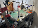
Yeah, that's basically the setup I arrived at myself after a while. But for applying the bluing compound I actually got most consistent finishes by using the coarse half of a sponge. I personally found that rubbing the Super Blue in using steel wool could result in the finish being scraped away if you apply too much pressure, though it's useful if you're touching an area up. With the rough half of a sponge you can get an even finish easier without worrying about going overboard.

Similar threads
- Replies
- 7
- Views
- 1,333
- Replies
- 8
- Views
- 2,900
- Replies
- 38
- Views
- 4,630
- Replies
- 19
- Views
- 3,438