1/350 Polar Lights Enterprise Refit - Build log

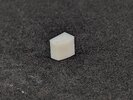
I did a little more modeling in Fusion and knocked out a cargo container. I printed out a batch and I'm happy with how they came out overall. However, as usual, I need to tweak things slightly. I'm happy with how the detail is reading (even though it's tough to see in the unpainted resin), but my original plan was to only print singles and assemble them into larger units. However, I don't like the way they fit together at the seams, so at minimum I think I'm going to do 2x1 and 3x1 assemblies the way the photoetch sets do.

I'll be adding these to my catalog of available prints, so if anyone wants a set, PM me.

Cargo Container 01.jpg
Cargo Container 02.jpg


Cargo Container 03.jpg
Cargo Container 04.jpg


PXL_20240610_030351195.jpg
PXL_20240610_030227194.jpg


PXL_20240610_030325715.jpg
PXL_20240610_030001241.jpg
 

Attachments

  • PXL_20240610_030308693.jpg
    PXL_20240610_030308693.jpg
    2 MB · Views: 32
I switched resin from Elegoo ABS Like White to Siraya Tech Fast Navy Grey, tweaked the model a bit, and baked in continuous supports around the bottom perimeter and I'm happy with the cargo containers. Now to get some paint on them, do a couple more PE figures, some touch ups,and I'll be ready to close up the shuttle bay.

1000016298.jpg


1000016299.jpg


1000016302.jpg


1000016304.jpg


1000016301.jpg


1000016305.jpg


1000016307.jpg
 
Love it! Stupid question, but how did you get those horizontal supports beneath the containers? I don't think I've ever seen that.
I modeled them directly in Fusion with the containers themselves. I came up with the idea for a continuous linear support structure when I was trying to get good prints of the replacement engine bells I designed for my 1/72 Eagle Transporter (although I've since seen several people come up with the same idea independently). The thin continuous support eliminates the pucker you often get around support contact points while simultaneously giving a larger contact area.

Here is an early test of one of the engine bells and the support structure for the Eagle. There are three contact areas in this case and some hollowing of the support structure itself to allow resin to drain. In this case the contact areas were still a touch too thick, leading to the rough part line on the inner ring and the chip in the edge of the bell. When you get the size just right, the support and the part separate almost perfectly.
PXL_20230721_145350788.jpg
PXL_20230721_175338272.MP.jpg

PXL_20230721_175317661.jpg
 
I modeled them directly in Fusion with the containers themselves. I came up with the idea for a continuous linear support structure when I was trying to get good prints of the replacement engine bells I designed for my 1/72 Eagle Transporter (although I've since seen several people come up with the same idea independently). The thin continuous support eliminates the pucker you often get around support contact points while simultaneously giving a larger contact area.

Here is an early test of one of the engine bells and the support structure for the Eagle. There are three contact areas in this case and some hollowing of the support structure itself to allow resin to drain. In this case the contact areas were still a touch too thick, leading to the rough part line on the inner ring and the chip in the edge of the bell. When you get the size just right, the support and the part separate almost perfectly.
View attachment 1837686 View attachment 1837687
View attachment 1837688
That's brilliant! Too bad I'm lacking those design skills!!
 
Back
Top