gt350pony66
Master Member

Gimme Sheltercracking work - its impressive to see what can be done with these fantastic Zvezda new kits - if it helps at all, I added the engine baffles to my Randy cooper model - these had slithers of metal foil on the insides which really helped deflect the blue light back into the engine nacelle and has seemed to damped and control the glare/glow when being photographed -
View attachment 781052
View attachment 781053
looking forward to more Imperial work from your kitchen table again soon
John
cracking work - its impressive to see what can be done with these fantastic Zvezda new kits - if it helps at all, I added the engine baffles to my Randy cooper model - these had slithers of metal foil on the insides which really helped deflect the blue light back into the engine nacelle and has seemed to damped and control the glare/glow when being photographed -
View attachment 781052
View attachment 781053
looking forward to more Imperial work from your kitchen table again soon
John
hey there, good morning John,
Thanks for the tip, I'd seen those reflectors on other guys stuff but wasn't sure how well they worked. I've got the HDA PE set for this but don't see those on the sheet? Unless I mistook them for something else. Easy enough to scratch though. So what I posted DOES work, good to know, plus the 3 reflectors, very cool. Thanks for chiming in to let us know. Escape has done a lot of experimenting on this, I've been trying to get the greebs done and re-assemble the bells, then I was going to try a few things cause I wasn't happy with just the extension tubes and like Escape, I didn't like seeing the LED's hanging out there. We're having a great time with the info sharing on this build, it's been exciting and it's great learning new methods of making things better. Thanks again and don't be a stranger. Also, the Merriest of Christmas' to you my friend :thumbsup
[/QUOTE]
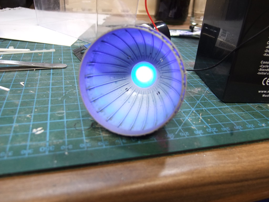
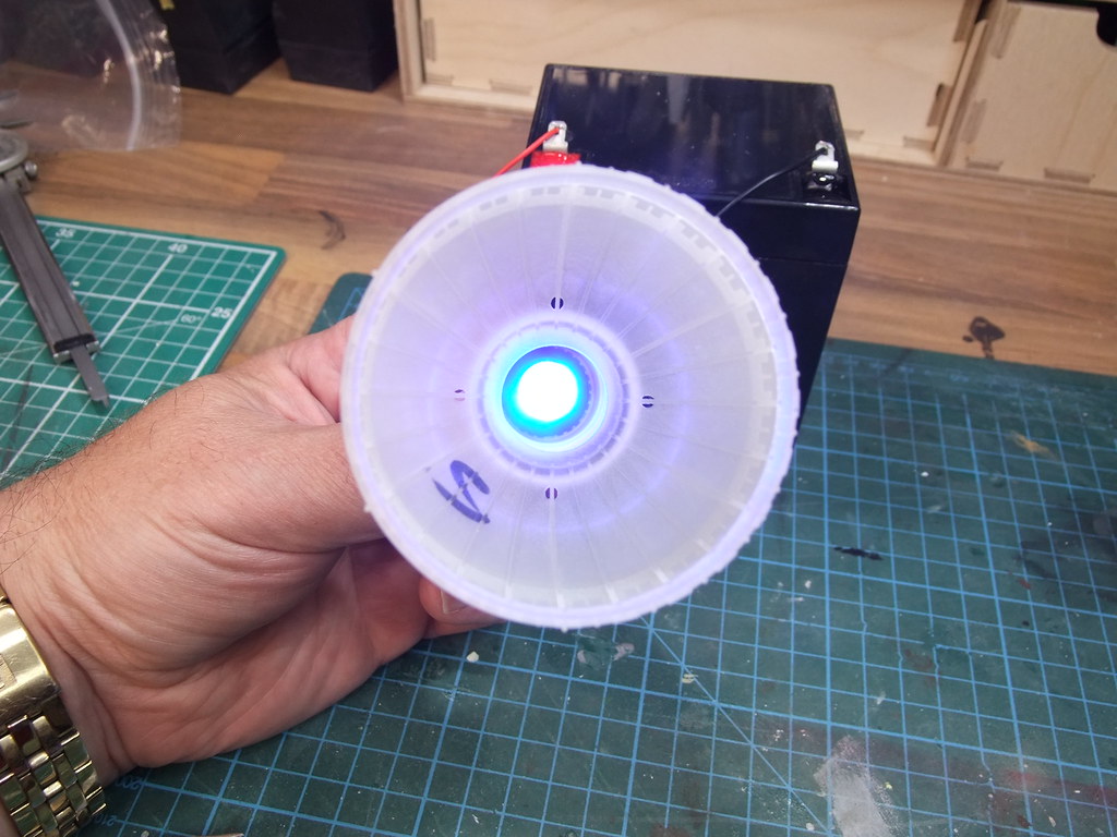
That looks cool like a car head light assembly!!
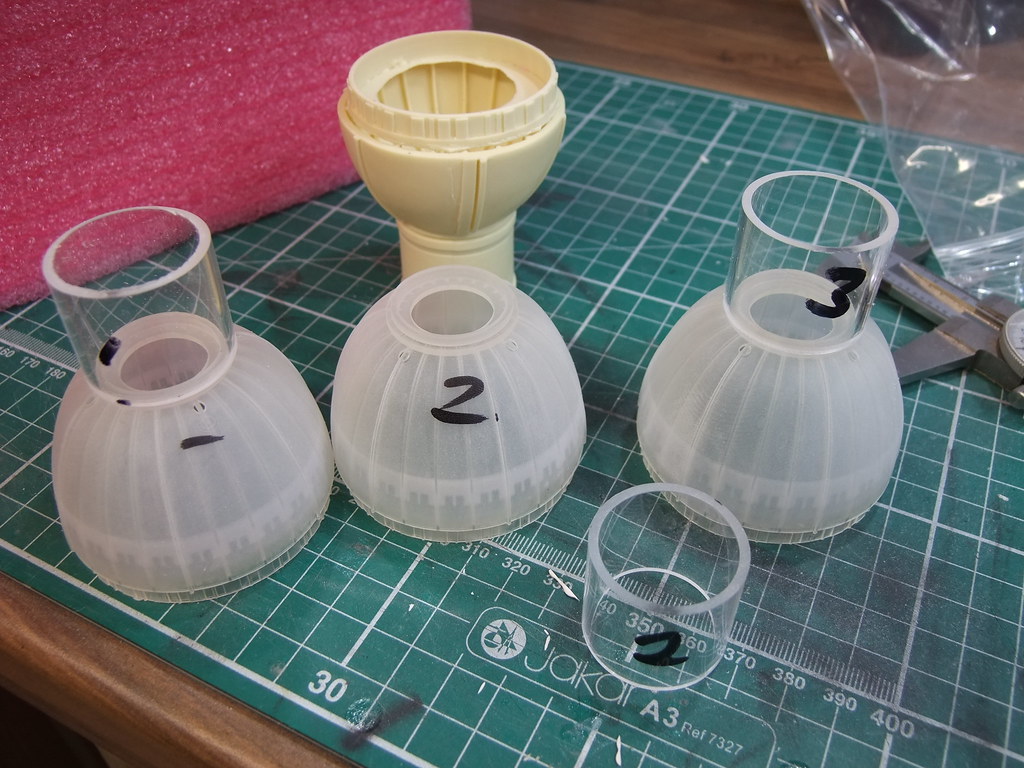
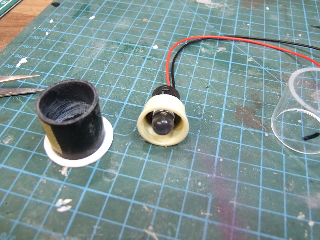
Gimme Shelter used a clear frosted cover over the LED to hide it. I will try that. It may let more light through while still hiding the bulb compared to the white cover I tested yesterday.
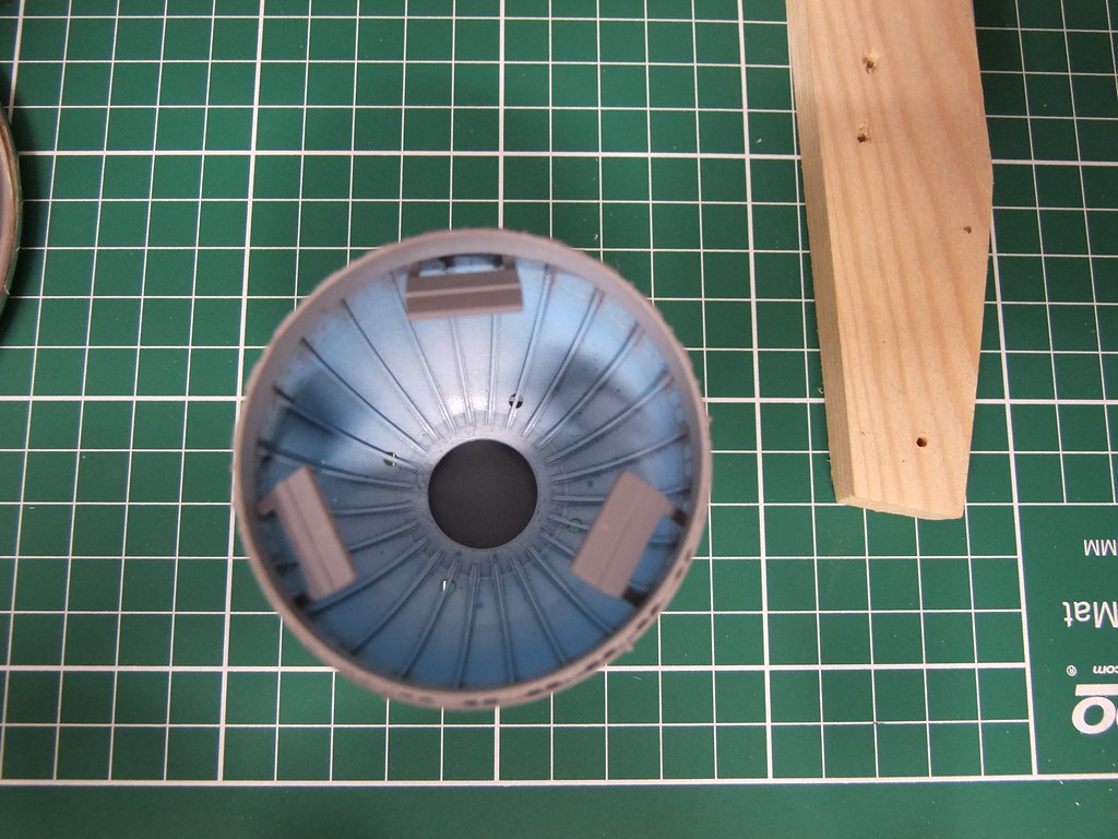
I think if you go with blue LEDs painting the inside of the bells blue and gray will enhance the blue glow look and if you go with white LEDs painting it white and gray will enhance the white glow look.
Of course painting it blue and gray with a white LED maybe cool also with a mixture of a white and blue glow.
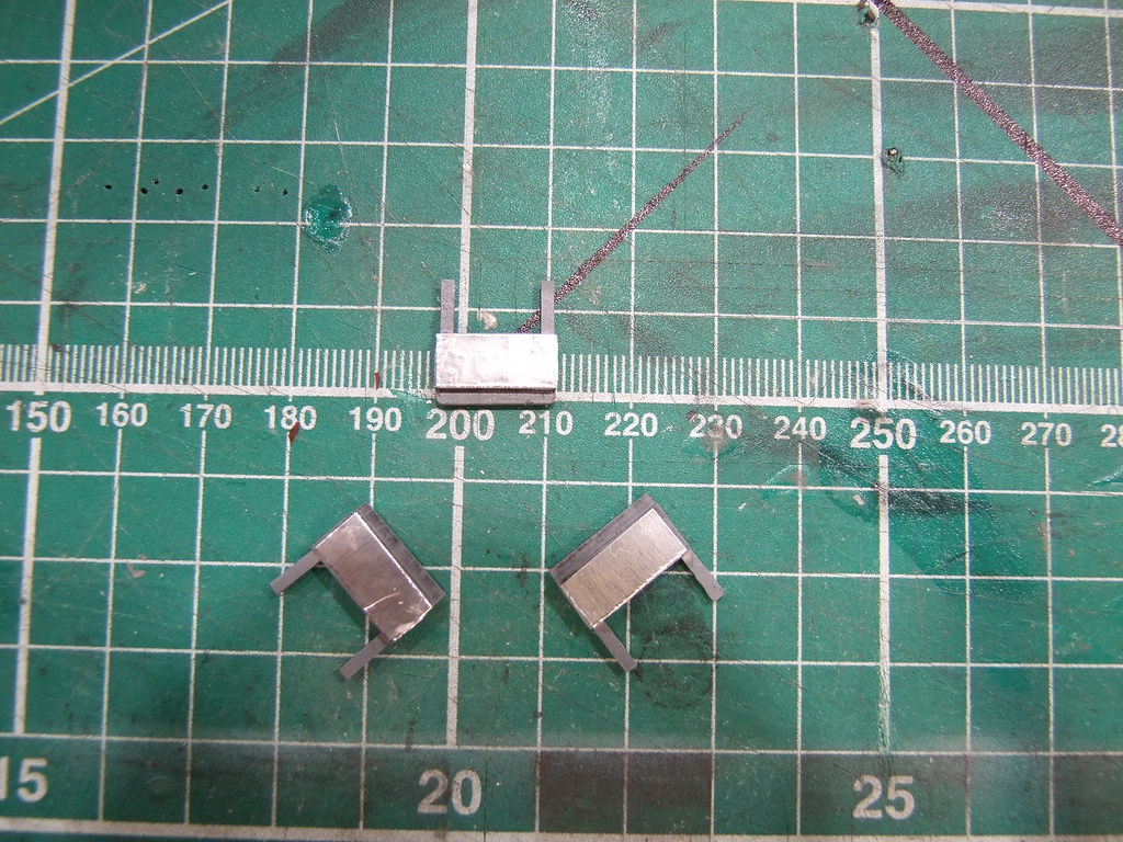
One of those above combinations and the 3 baffles with a mirrored backing on each bell may be all that's needed to get the look we are all looking for......
[/QUOTE=gt350pony66;4373418]
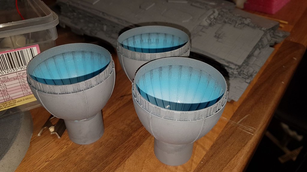
View attachment 781050I was thinking something like this...a styrene sheet cone that will still let the light through but conceal the LED, and reflect the light back into the bell illuminating it better...in theory of course. Sorry for the kinder-garden drawing...I did it on the quick but you get the idea, right? I'm going to give it a whirl this weekend and see what it does. perhaps a simple round cut piece of styrene bent to a slight convex would do it and not necessarily a cone shape?
Hi Ged
Its actually an accident - I ran out of the original batch of 5mm white LED bulbs during the fibre optic set up stages and ordered a second batch of cool white LED bulbs. Unknown to me, I ended up building a kit with 2 shades of white LEDs. I tested each bulb before plumbing them in to the hull, and tested them once they were tubed up to the fibre tips but all this was done in daylight and did not show the difference in the 2 shades of bulbs that had got mixed up until I eventually lit the model up one night in the dark - to my horror, I had a multi-coloured destroyer !! - It actually worked to my advantage in the end; so many people have commented on the lighting shade variations saying it makes a difference and complimented me on working a way to make this big monster of a kit look different using alternative white shade bulbs - I've never confessed to it being a build oversight until now...
Hi mate
Always looking to help an Imperial flagship builder out so no problem and always happy to offer a tip - below are some pictures I took way back when I first got my 3D printed engines for my RC kit - I asked one of my model club members about the main engine bulbs and he told me to place them in the tube as far up inside as possible so that the illuminated bulb did not protrude and the light would emit equally - I confess to not knowing really how to best approach this but can offer you the pictures I took below as guidance - I know its a larger scale but the process worked. I also airbrushed the engine nacelles a shade of blue and eggshell yellow/white for when the lights were not on. The clear frosted diffusing material added the final touch to control the glare from the 10mm blue LEDs and the mirrored baffles that I scratch built have made it easier to look at and seem to add a tad more realism - hope this all helps.
https://farm5.staticflickr.com/4490/36799225774_2b54f464cd_b.jpgDSCF7174 by John Leah, on Flickr
https://farm5.staticflickr.com/4482/37509548101_e136f1caaf_b.jpgDSCF7157 by John Leah, on Flickr
https://farm5.staticflickr.com/4390/36923530811_1b4967b71e_b.jpgIMG-20170802-WA0004 (002) by John Leah, on Flickr
https://farm5.staticflickr.com/4304/36041956441_5058980b81_b.jpgDSCF6967 by John Leah, on Flickr
https://farm5.staticflickr.com/4330/35336737474_7f3e0b3e00_b.jpgDSCF6968 by John Leah, on Flickr
https://farm5.staticflickr.com/4302/36041955631_8d89deb703_b.jpgDSCF6969 by John Leah, on Flickr
https://farm5.staticflickr.com/4307/35336737004_9a70982004_b.jpgDSCF6970 by John Leah, on Flickr
https://farm5.staticflickr.com/4302/36041955001_7826cae821_b.jpgDSCF6971 by John Leah, on Flickr
https://farm5.staticflickr.com/4307/35336736544_09cbb7d57d_b.jpgDSCF6972 by John Leah, on Flickr
without the clear frosted diffusing material
https://farm5.staticflickr.com/4314/36041954491_aa7454f3ca_b.jpgDSCF6973 by John Leah, on Flickr
https://farm5.staticflickr.com/4301/35336736154_ab68d62b00_b.jpgDSCF6974 by John Leah, on Flickr
May the Force be with you, Always..
John
I haven't gotten to the assembly of the engine section to the hull yet. Probably not for a couple of months yet anyway. Once I get the trench greeblies done on both sides of the bulk hulls top and bottom and all holes for FO drilled, I will then likely glue the engine section to the bottom hull section. I plan to use carefully carved styrene sheets angled at the same degree to shim the top edges to the top of the engine area assembly when the top hull is glued down to the bottom hull. I will have 1.5 mm to fill along the entire top of the engine assembly, as that is the height I raised the trenches. That will happen after light-blocking, fiber and electronics are run and placed, and the model is fully greeblied and lit. It will likely be the very last assembly I do before priming and painting.
the only downer about raising the trenches is, I'll have to fit, finish, paint and wash before I install the pieces cause I've already done paint and FO on the existing :unsure
With all this raising the trench talk I have the bug too!!
I have all the FO holes drilled in the wall that's part of the bottom hull section. I was thinking of adding a strip of .60 x .60 all across the top of the wall to raise it approx. 1.5mm but not have to add any more FO or add any detail to it. That .60 (about 1.5mm) is enough to give the trench more height but small enough that you don't need to add any FO or detail to it since it will be up at the top of the wall where the overhang will be.
I will do the same to the top of the engine block by adding a.60 strip and have it slightly past the edge and filing it on the same angle it already has
I will also not mess with the hangar opening.........just add the .60 strip over the top of the opening so that will be .80 thicker.
If I decide to raise the trench I think I will do it that way.
Just checked heights again .60 is 1.5mm.......I may go with .40 which a little shorter at 1mm and would not need any FO or detail added to it. That will give trench 1mm of extra height and I think would look good. The .60 at 1.5mm I think would be fine also not needing any FO or detail since its at the top under the overhang.
I'm right there with you brother, my thoughts as well. I went to the hobby shop at lunch and bought some .60, and some .40, just in case I decide I can't got with the taller stuff. though I think I'm going to try to add some FO, but only in the blank areas that exist below it. I'm also going to give it a go on some of the extra greeblie, but no more than I can hand paint and blend well enough since I've already done the paint, wash and FO on the lower. I suppose, like you say, if I add the stuff to the upper, I can mask and shoot cause there's no FO on the edges to worry about. The extra greeb that spans lower, I'll have to hand paint, shouldn't be too bad. Tricky work at this stage, but I think it'll be ok and well worth the effort. man this is fun aint it?! :thumbsup
- - - Updated - - -
And I think I'll leave the hangar openings alone as well
What size are you leaning towards........If you go with .40 their is not much you can add its such a small 1mm space. You can take small strips of .40 and glue in front of the .40 that you raise the wall with. Cut different sizes maybe cut little teeth into it for some design. If you have the half round .40 you can also glue small piece of that to the wall. On the parts of the wall that are thicker I plan to use wider .40 x .125 or .60 x .125 so there is more gluing area for the top.
Well, I haven't sat down with it just yet, but I'm going to really try to go with the .60 so I can do a little FO and greeblie, but if it looks like it's gonna be a hassle, I'll do like you said with the .40. Got home late today and I gotta sit down and pay bills n crap. then try to add some weather to a 1/72 P38 that I'm giving to one of my boss' for his office. He's an RC nut. got like 4 really big WWII fighters...like 6 ft wing span big. then he's got a few statics in his new office, but not a P38, and I have two. One alum finish and one olive drab with invasion stripes. He's getting the alum finish cause his other office models are that as well. I'll let you know what i decide on the walls. sounds like you're going .40?
Even going with the .60 I think you can get away with not adding any detail and it would look good and no one would ever know.
Well, I'm going to give it whirl, if it doesn't work, it doesn't. As far along as I am, and paint being done to the big pieces and the stock trench walls, it will be tricky to do but I think I can pull it off. It'll just be tedious and cumbersome to say the least. I've got a stiffy to get the extra FO and greebs!!:lol
Post that stuff when you can though Escape, it will most likely aid in my final decision to attempt it or not. I likely won't sit down for it till the weekend anyway and I sure don't want to make a mess out of this thing at this point. I did just finish the engine panel though but I won't post pis till I'm at work...the laptop just doesn't cooperate with getting the things right side up :facepalm
Invar, thanks for the encouragement to go for it. whats the worst that can happen...I'll have to do another ISD...now that wouldn't be any fun at all :lol