Treadwell Droid Build

Paul6700

Well-Known Member
RPF PREMIUM MEMBER
UPDATE: Final droid update on Page 7.

General 2.jpg


Hi All,

I thought I would create a build log for my WED-15-77 Treadwell Droid from Star Wars, A New Hope. There was a Star Wars Storybook that had shown a great picture of the droid with Luke that made me remember it as if I had seen him in the movie. Ever since then I have wanted my very own Treadwell.

Here is a picture as refresher, he was included in a deleted scene more recently. However he also made into the Jawa Sandcrawler and also as a mechanic on Hoth in The Empire Strikes Back.

View attachment 259688

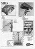
A little about my background, about five years ago I joined the R2 Builders club and built my first droid R2-M5. Basically he is a red version of R2-D2 and shortly there after I built a scaled version of the MSE-6 droid. Now I want to build my own Treadwell. I started by joining the Treadwell Builders group and found that the few members there created several blueprints for the main areas of the droid. I was also able to get a photocopy of an article that was written in 1977 by Electronics Today International. Here is a low rez version of the page I got from the publisher.

View attachment 259689

Now onto the build.
 

Attachments

  • Treadwell.jpg
    Treadwell.jpg
    15.1 KB · Views: 740
  • n_a 1.jpg
    n_a 1.jpg
    219.3 KB · Views: 791
Last edited:
The blueprints (found at the Treadwell Builder's Yahoo Group) outlined the basic measurements for seven areas of the droid; the head, the neck, the body, the base, the treads and the wheels. My goal is to create as screen accurate a droid as possible and have it function. So I want it to be able to move on its treads as well as look around with the head. In addition I would like to get some arm movement from his upper arm.

I started with the body as I felt all of these parts could be made with either PVC or ABS pipe from a hardware store. So I printed the blueprint for the body and headed off to the hardware store with a tape measure.

With a variety of fittings and different diameter pipes I was able to piece together the body in one day.
1. body.JPG

I decided to tackle the head next, using balsa wood and the club blueprints, I created two identical tapered rectangles that are bolted together using 1/4 inch threaded rods and nuts.

2. head.jpg
Sorry the pictures are not that great as this was done some time ago and I should have taken more pictures. I will get better I promise.

The base I fabricated out of hard wood so that the sides would be as straight as possible. Again following the dimensions provided by the group.
3. photo3.JPG 4. photo2.JPG
After cutting the sides to the right shape and dimension I used one inch square stock to connect the two sides. I also wanted the top of the base to be mounted into the sides so that there would be plenty of strength. I also finished the bottom so that I can mount batteries and motors inside.

The front and back of the droid is wrapped with sheet aluminum for roofing. It comes in a roll and I cut it to length and screwed it into the one inch square stock. This allowed me to create the shape in the front and back very quickly. In addition to the base I made plate that connects the body to the base using 1/4 inch plywood and the one inch square stock.
 
Last edited:
The base was completely coated in Bondo and sanded smooth. I did not want any of the wood grain showing through since he should be made of metal. I also fabricated the logic housing, which attaches on either side of the body. I reinforced the inside with wood because I figured little kids might think this is a good place to stand.

5. Painted Base.jpg

On the inside of the base I made a spot for the motors to sit and on the opposite side I slotted the sides of the base and created a well for my tension system to be installed. I am using a rubber tread and a friction system, so I need some way to add tension to the track.
 
Last edited:
Thanks Drac, I am extremely speedy!

With the base painted and the body attached it was time to get the neck figured out. I used a caster as the swivel mechanism with a servo mounted in the middle. It was covered with a piece of PVC to hide it.

7. Test Head and Neck.jpg

I fabricated the neck using plywood and aluminum and balsa wood ends to try to make the neck look like what was originally used.
9. eyes.jpg 10. Neck Servo.jpg

The body and the neck were painted silver as a base coat.
8. Neck and Body Painted.jpg
 
Wow! What a build!

Two points that have fascinated me about this droid are the driving wheels and the 'eyes'.

Are the driving wheels at each end part of some sort of electric motor armature, or are they drive wheels for some type of rubber belt?

And are the eyes really some sort of 35mm slide viewer?

Loving what you have done so far, and am looking forward to lots more pictures, please.
 
Thanks for the kind words Blaxmyth. I ended up custom making the front eye lenses out of styrene because I could not find any information on what was originally used. But you have inspired me to try to find out.

The original wheels were likely made of wood, however I went with rubber wheels. The very front wheels are the drive wheels and the very rear wheels are used to keep tension on the track. I will post some pictures of that area shortly.
 
I was really concerned about the weight of the head. So I made the eyes as light as possible. I started with a styrene box that I glued together and painted black on the inside.
2013-11-28 13.03.46.jpg

Next, I painted the inside of a clear medicine cup black and the outside I painted silver to simulate a camera lens on the inside of the eye.
2013-11-28 13.04.50.jpg

The frame is made of styrene and painted to match the rest of the head.
2013-11-28 13.15.10.jpg

The medicine cup is glued inside the box and the box and lens was slid into the head. I used high bond tape to affix the frame to the head.
2013-11-28 13.05.32.jpg
 
I used aluminum and attached a standard servo for the up and down head movement.

2013-11-29 11.41.24.jpg

Then attached that to the neck. You will notice I totally reconfigured the neck. The other neck was just not strong enough.
2013-05-18 17.51.28.jpg2013-11-28 13.30.42.jpg

Here is a close up of the neck motor and gears.
2013-11-27 23.38.05.jpg

I am not happy with the way it looks, it is not screen accurate. The original was the head of a tripod or camera mount, but can't figure out which one. I may create a 3D model and print one that is closer.
 
The arm brackets are made of sheets of tin. Easy to cut and bend and strong once bent into a shape. Here is a close-up of the finished bracket.
2013-11-27 23.35.58.jpg

There are five arms total on Treadwell so I made a template based on this simple design.
2013-11-28 22.26.39.jpg

This is what it looks like with an arm attached. Simply drilled a hole through it and the arm.
2013-11-27 23.36.09.jpg

I have only made two of the five arms so far. And the word made is a very loose term. I used a Craftsman 26-3/4 Inch Pick-up Tool for one of the arms and I used the temperature gauge from my multi-meter for the other arm. I threaded the sensor for the temperature gauge through two brass tubes that nested together. The portion on the end of the arm is the part that connects to the meter. I can now take Treadwell's temperature whenever I want.:D
2013-11-27 23.58.04.jpg2013-11-27 23.58.27.jpg2013-11-27 23.59.04.jpg
 
The treads have been debated a lot over at the Treadwell Builders group. However I think I figured out what they used on the original. There is a close up of the track in Electronics Today International and here is a picture of mine.
2013-11-29 12.44.08.jpg2013-03-10 19.35.41.jpg
It is a 70 inch 1/2 inch pitch blower belt turned inside out. The 3 inch width of the belt and the 70 inch length fits perfectly. I went with a hard rubber wheel with a outer hub. There are twelve 4-1/2 inch x 1 inch idler wheels and eight 4 inch x 1-1/2 inch drive and tension wheels. I used a cut up fan belt riveted to the blower belt and the wheel straddle the fan belt.
2013-11-27 23.57.23.jpg
 
Treadwell is able to look left and right and is able to look up and down. In addition, he can move around on his tank treads. I am using a 12 volt 25 amp speed controller hooked up to a R/C receiver to drive him around. The eye movement up and down is controlled by a single servo.

The motors are connected to the front wheels via a chain drive.
2013-11-16 14.21.04.jpg 2013-11-16 14.21.16.jpg

To look left and right I am using a hobby speed controller connected to a separate battery. Here is the electrical plan for the whole droid.
Treadwell Electrical Plan.jpg
 
To control Treadwell, I am using a four channel radio and an iPod for sound. I will be expanding his options in the near future, however this is all I need for the moment. I am using an app called LiveTrax on my iPod which I use Bluetooth to connect to a Bluetooth receiver and a low budget amp on the droid. LiveTrax stays on and plays one sound at a time and then waits for your next input.

2013-11-29 15.07.35.jpg 2013-11-29 15.07.43.jpg 2013-11-29 15.09.02.jpg

I used a small strip of aluminum bolted to the front of the transmitter case and a hard case for the iPod.
 
Thanks Xingshen, I got the belts from an EBay store called Dale Wilch. He has a website dalewilch.com that sells new and used racing parts. I bought the 70 inch x 3 inch wide square 1/2" pitch supercharger street blower drive belt. You need two.
 

Your message may be considered spam for the following reasons:

If you wish to reply despite these issues, check the box below before replying.
Be aware that malicious compliance may result in more severe penalties.
Back
Top