Type-15 Shuttlepod from Star Trek TNG

Update:

I have moved my attention to the rear bulkhead details. Comparing the concept sketch to screenshots there are many discrepancies.

kRCM14t.jpg

Screenshots from Times Squared.


b7qeLvD.jpg


nezmJBj.jpg

I started by editing the concept sketch to match what I saw on the screen shots.


5ZBMUR4.jpg

I then added these details to my 3D model. The only areas I could not see on camera were the lower corners of the bulkhead and how the two plant-ons terminated. I went with the assumption they were as depicted in the concept drawing


IxpNDXy.jpg

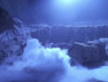
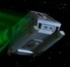
There are two plexiglass panels in the bulkhead that represent isolinear chip arrays.

Close-up of the isolinear chip arrays in screenshot from Times Squared.


ukKnmhR.jpg

These panels did not cover any actual chips but appear to be similar in construction to an LCARS panel, backlit to give the appearance of isolinear chips.

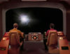
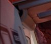
Closeup of the central isolinear chip array in screenshot from The Price.


s1uJcaZ.jpg

Closeup of port side isolinear chip array in screenshot from The Minds Eye.


h8I6kLc.jpg

I have seen this method used in many TNG sets. For reasons explained later I referenced the ops station on the bridge. Initially in Season one there was no isolinear chip display.

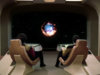
Ops station in screenshot from Encounter at Farpoint.


dz58SlA.jpg

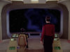
Starting with season two an isolinear display was added to the base of both the ops and con stations. This was also the flat panel display with no actual chips inside.

Ops station in screenshot from Where Silence Has Lease.


e5Sb7Qk.jpg

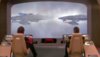
The use of this type of panel appeared to be consistent thru season seven

Ops station of future Enterprise in screenshot from All Good Things....


qQdZ5fk.jpg

The original Enterprise-D set was destroyed in the making of Star Trek Generations. A replica was made for the Star Trek the Experience attraction in Las Vegas with input from production designers Herman Zimmerman and Michael Okuda. Even so, this replicas is far from cannon. A noticeable difference was the addition of a speaker grille in the support pylons for both the ops and con stations. Also the base of the chairs are the non-swiveling bases seen in season one while the upper portion of the chair has the design used in seasons two thru seven which used the swivel base.

Ops station of bridge replica in Star Trek the Experience, Las Vegas

2SuhoMX.jpg

The replica was dismantled and auctioned off in 2010. Ops station of bridge replica from Star Trek the Experience from Propworx auction catalog 2010


ok4FLry.jpg

The ops station was purchased by the collector Gerald Gurian who posted pictures on his site. These images reveled that for the replica they replaced the flat panel chip display with an actual chip array. This is visible with the smoke colored plexiglass removed. I am assuming this was done to enrich the visitors experience, since most TV props provide an illusion and are not as impressive in person.

Ops station of bridge replica from Star Trek the Experience from collector Gerald Gurian.

kusP3kr.jpg

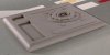
Gerald was also thoughtful enough to include close-ups of the chip array with a tape measure for scale.

Isolinear chip array in ops station of bridge replica.


uHDwo8R.jpg

Isolinear chip array in ops station of bridge replica.


Qp84Hun.jpg

Isolinear chip array in ops station of bridge replica.


1aI0olA.jpg


How all of this is relevant to the shuttlepod, I want my shuttlepod replica to be just as rich in detail upon close inspection, so I am opting to do the same. Since Herman Zimmerman and Michael Okuda contributed to this replica, this is as close to cannon as I'm going to get regarding isolinear chip placement.If desired I can easily fall back to a flat panel LCARS type display in the same openings, matching the original mock-up.

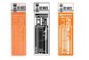
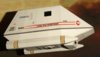
There were many variations in the isolinear chip props, both in size and markings. I am opting for the 1" x 3 1/4" x 1/8" translucent plexiglass originally with the circuit design silk screened on one side. There was a minor variation in the pattern near the label, but that was mostly obscured by the label. The labels had a vertical black bar and a thinner horizontal black bar. The black pattern was broken up with five randomly spaced horizontal white lines with a white rectangle in the top segment. The printing on the label consisted of two numerals, a hyphen and then four numerals.


Screen used isolinear chips.

Eagr5Bl.jpg

I did find a fan made circuit pattern and label and used them. Upon closer inspection I found the circuit pattern is inconsistent with the on-screen props and I made some modifications. I have created some 3D models of the isolinear chips with labels to use a place holders for now and have incorporated them in the 3D model for my storage unit. I have also added the isolinear chips to the 3D model of the bulkhead with chip storage arrays.

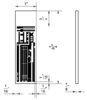
Rear view of 3D model of the bulkhead

UWQQOYW.jpg

I will come up with some kind of light boxes for the chip arrays and LCARS display
 

Attachments

  • PGuL5Ew.jpg
    PGuL5Ew.jpg
    276 KB · Views: 117
  • moV6DtA.jpg
    moV6DtA.jpg
    220.2 KB · Views: 130
  • vDAvQjQ.jpg
    vDAvQjQ.jpg
    53.3 KB · Views: 118
  • 6jgeQTg.jpg
    6jgeQTg.jpg
    73.9 KB · Views: 160
  • JvPvyWC.jpg
    JvPvyWC.jpg
    38.9 KB · Views: 186
  • DBq0c8F.jpg
    DBq0c8F.jpg
    89.6 KB · Views: 185
Last edited:
Update:

I corrected the discrepancies in my isolinear chip model.

On the left is a screen used prop for the collection of Doug Drexler. The chip measures 1" X 3 1/2" X 1/8". I lengthened my model accordingly.
In the center is my digitized version of the chip.
On the right is a corresponding orthogonal view of my 3D model of the chip.

DBq0c8F.jpg

Here is the layout of the circuit pattern and it's placement on the chip. Rather than using the silk screen method for the circuit pattern I intend to laser etch them on both sides. This will be more durable and have a better appearance close up.

JvPvyWC.jpg

This is a quick render of the completed 3D model.

EudmJ7I.jpg

For the entire shuttlepod I will need:


  • 5 light blue chips
  • 5 dark blue chips
  • 13 yellow chips
  • 39 green chips

Altogether 62 individual chips.

I intended to print 62 labels, each with a unique number and bar code. I was hoping to gather this information from authentic props, but it is unlikely I will find 62 authentic labels among all the replicas found online. So far I have only found 13 images of labels on line that are "probably" authentic:


  • 00-0027
  • 00-3849
  • 01-2462
  • 02-8623
  • 03-0262
  • 06-5253
  • 09-1792
  • 24-2267
  • 42-8437
  • 53-8623
  • 54-0927
  • 55-3732
  • 86-5023

For all I know this may have been the full extent of the numbers used. You would probably never see them on screen anyway. I will either use random numbers and bar code patterns to create the rest or just repeat the known values.

It's all about the details.
 
Last edited:
Update:

My first test fitting of the control panel in the 3D model with the Ops and Con stations in place. The colors are not the final palette, this is just to check the design geometry for fit and form.

HGRBlBM.jpg


yjN8PK8.jpg


qxkDA6x.jpg
 
Last edited:
Update:

More R&D on the control panel.

It was impossible to get any orthogonal views normal to the LCARS panels, so I had to make some calculations based on reversing the perspective and skew. Once I had the LCARS installed in the control console I was not satisfied with the aspect ratio of the LCARS panels. The image below is a composite from The Minds Eye and Devil's Due. It is the closest I could come to a view looking straight forward at the level of the control panel.

rKFj8uF.jpg

The Minds Eye/Devil's Due composite


It has always puzzled me how they attached the control panel to the interior of the fuselage. It didn't just hover there and there are no good hard points at the level of the panel to attach to. As with the composite from The Minds Eye/Devil's Due the underside of the panel is normally in shadow and there is no visible means of support.

hYtjakF.jpg

The Most Toys

HaS58uy.jpg

Production still image, Times Squared

YSTKIDM.jpg

Times Squared
I did find one small exception. There is a shot in The Ensigns of Command below where the interior is brightly lit and you can just see there is a skirt coming down at an angle where the vertex of the control panel meets the inside of the fuselage. The edge of this skirt appears to follow the angle of the wall which (not clearly shown) would come to rest on top of the structural member that runs laterally where the upper and lower fuselage meet.

ZBsGAcY.jpg

The Ensigns of Command​

I Experimented with the angles and found that a skirt angle of 45° from vertical appears to match the angle in the image above.

aCW82nn.jpg

Isometric view with skirting

6PAnmlN.jpg

Front view with skirting
The top deck of the panel has a few challenges. There are many views of this from which I could compare the angle of the top creases and the pattern and widths of the graphic tape used.


Qt4ldCW.jpg

The Ensigns of Command


UzlfVaS.jpg

The Price


xaEsZMv.jpg

The Price


BHjBzNW.jpg

Identity Crisis​

One thing no on screen image clearly shows was how the top deck intersects or otherwise terminates under the front view port. While reviewing some of the HD screen captures I noticed something in the final scene from The Ensigns of Command. For whatever reason they decided to put the plexiglass panel in the front view port for the shot below. In that panel I can see both the reflections of the graphic tape (large box) and the edge of the top deck (smaller box).


ek6xOUD.jpg

The Ensigns of Command
From that I can see that in the original mock up the top deck did not extend even to the edge of the view port. Using the graphic tape as a reference I can match the approximate length of the deck. Since this was never really shown on screen I will probably use artistic license and extend the deck into the nose. It would look unsightly otherwise for anyone directly in front of, an angle from above, or from inside the mock up.

Below are some orthogonal views of my 3D study model.

a2bDhTP.jpg

Multiple views with skirting

Working out the framing plan will be interesting with all the compound angles.
 
Last edited:
Update:

I have been reworking the 3D model for the top plant-on. This was first and most clearly seen in the beginning of Times Squared

NQn5baD.jpg

Times Squared

There was also a good profile shot mid-episode where you can see the overall length of the plant-on compared to the width of the hatch


2LWgOYV.jpg

Times Squared

There was also a fairly good shot in The Most Toys.


quVfNMN.jpg

The Most Toys
A not too clear shot of the miniature in Times Squared.

DthoKQp.jpg

Times Squared (miniature)

A better shot of the miniature in The Minds Eye

TIEopZP.jpg

The Minds Eye (miniature)

Most of the plant-on consists of simple rectangular forms with rounded corners. The circular feature front and center is a lot more complicated. I have noticed this same circular feature used as light fixtures elsewhere in other episodes. Special thanks to Jörg Hillebrand for pointing out the origin of this feature in the ceiling of the turbolift shaft in Star Trek V.

UYQUIZd.jpg

Star Trek V

This does not look entirely like a repurposed consumer product. The center of it appears to be a recessed light fixture with a standard 4" spot light. The rest of it appears to be vacuum formed styrene or similar thermoplastic. Since the premiere Star Trek V and the first appearance of the shuttlepod in season 2 were both in 1989 it makes sense that these features were from the same source.

J2AoTSU.jpg

Star Trek V

Using a 4" diameter spotlight as a scale reference, I created a 3D model to approximate the circular feature as closely as possible. I intend to fabricate it with built-up layers of 1/4" and 1/8" MDF. The center cylinder I will probably machine from PVC pipe.

Y4KLyLo.jpg

3D model​

It appears that this same feature was used as a plant-on for the aft hatch surrounded by a thick ring. This is only seen twice on the mock up. First in in The Most Toys and then in Power Play (just before it's blown off).

rOAz6oe.jpg

The Most Toys

UuDkXrR.jpg

Power Play
It can be seen on the miniature. the best shot I have is from In Theory. There is a discrepancy between the plant-on on the mock-up and the one on the miniature. On the mock-up the circular feature appears to be inset inside a thick ring. On the miniature the circular feature appears to be protruding out from the thick ring. It is always possible that as part of its function the disk extends during flight. I intend to model it in the non-flight configuration of the mock-up.

VOweMZS.jpg

In Theory (miniature)​

I believe this same circular feature also incorporated in the plant-on on the underside of the miniature. You only get a glimpse of it in Times Squared

2MozNUv.jpg

Times Squared (miniature)

There is a slightly better view in the HD remastered The Minds Eye

rBSWfwJ.jpg

The Minds Eye (miniature)
And I have a partially obscured view from an image taken of the miniature when it was on display for Star Trek: The Tour in Long Beach. There was a support wire that I was able to digitally remove but the shadow it cast obscured some of the detail.


rfRd6dc.jpg

Star Trek: the Tour, Long Beach (miniature)

I'm not sure if I will make the plant on for the bottom. It would be hard to see and appreciate. If I do it will have to be removable so I can get a pallet jack or a fork lift under the mock-up to transport it.
 

Attachments

  • 25h3bqo.jpg
    25h3bqo.jpg
    21.3 KB · Views: 112
  • WMwOlDS.jpg
    WMwOlDS.jpg
    396.3 KB · Views: 81
  • FEVkNdx.jpg
    FEVkNdx.jpg
    2.7 KB · Views: 85
  • 4K5nZHD.jpg
    4K5nZHD.jpg
    142.3 KB · Views: 87
Last edited:
Project update:

A huge thank you to Lt.Washburn on the Fleet Workshop Forum for identifying the source for the isolinear storage prop.

N4xrPb2.jpg

It is the top cover of a Clay Adams QBC Hematology Analyzer from Becton Dickinson. There are a few variations but so far model 4526 looks like a match, at least for the prop used in the shuttlepod.

LsORCek.jpg


Mf5xtkj.jpg


uCOQYxe.jpg


OqGA1WP.jpg


rGIyssM.jpg


I would love to get a hold of a non-functioning unit for a decent price.
 
Last edited:
You're welcome. I've been looking off and on for a year or so. Actually last year I had done a lot of research and "discovered" the seats used in the shuttlepod, only to find out you had also figured it out yourself. Which, brings to mind something I was going to suggest. If you do get to the point of building a shuttlepod replica, I encourage you to source vintage seats, rather than go with the current versions. I'd help you look for some decent examples if you're interested. There have been examples that go for sale occasionally that I've seen. I just think the extra accuracy will put things over the top.
 
I encourage you to source vintage seats, rather than go with the current versions. I'd help you look for some decent examples if you're interested. There have been examples that go for sale occasionally that I've seen. I just think the extra accuracy will put things over the top.

Auto upholstery is not included in my skill set, so this is an item I will have to purchase. Naturally since I'm into the details, if I can find the vintage seats at an affordable price I would prefer them to their replacements. If you happen upon a pair please let me know.
 
Auto upholstery is not included in my skill set, so this is an item I will have to purchase. Naturally since I'm into the details, if I can find the vintage seats at an affordable price I would prefer them to their replacements. If you happen upon a pair please let me know.

I've been meaning to find some car forums online, there's a whole community of people who probably know someone with vintage seats in their muscle car done up in the 80's. Probably a fair number that would be in good condition or even already reupholstered, who knows.
 
I'm still on the lookout for the original version of the Scat Industries Procar Rally bucket seats for the cabin to come on the market. I spotted images of the two below but apparently they were sold years ago in that the page now redirects to Walmart. The images do provide a resource showing details of the seats that were never on camera.

wsXVh4g.jpg


SPVRbIV.jpg


ycwQoRS.jpg


VbvACt6.jpg

I found some additional images of the seats installed in vehicles.

nycIwCV.jpg


JgTngLw.jpg


fJQcq5I.jpg


0VILE5E.jpg


AFJbxl3.jpg

If anyone spots these for sale, please let me know. It may take months or years but I'm patient. If nothing else I would love to borrow one long enough to get some scans and measurements so I can create an accurate 3D model.

To identify the desired version, the current version (below right) is shorter, wider, has 6 vertical seams while the version used in the prop (below left) had 7 vertical seams.

NmA3qwv.jpg

Also the version used in the prop had a quite elaborate set of adjusting leavers on the side.

XNGZ2Vw.jpg
 
Last edited:
An update on the Isolinear chip storage unit. I managed to acquire two QBC Readers. The part on the left is the top of a unit on loan from Lt. Washburn and is of the same type used for the on screen prop. It is a one piece design and was slush cast. The parts on the right are from the top of a later unit and belonging to me. This is a 3 piece design that was injection molded.

DivNqhg.jpg

X65ftgo.jpg

zaIFwtY.jpg

W72MMxB.jpg

While my unit is not screen accurate as is, with some modifications it will be close.

aghCsFU.jpg

One advantage is the injection molded shell is heavier and more durable that the slush cast shell.
 
Regarding the isolinear chip inserts, I have several of the chips that were used on the recreations from STTE. As a cost savings measure, the isolinear chips were not full chips, instead they were only an inch or so tall, just enough to show the label and give the appearance of the entire chip was inserted into the device. You could do something similar, but then have a few "hero" isolinear chips that are the full chip and can be removed from the device.

If you're interested, I can dig them out of storage and send some reference photos.

Yes I am interested. They may not be screen used props, but being licensed by Paramount they are close enough to canon for me. If you could get some pic's that include a scale that would be fantastic.
 
Update:

Doug Drexler posted some behind the scene pic's of the full size mock-up after it was redressed as the Type-18 shuttlepod for DS9

35j9t3n.png


The mock-up was only used for interior shots.

w9tr86.png


The mock-up retained the gull-wing door design which reveled some additional details of the hinge construction not seen in the Type-15 images..

96gsy9.jpg


The fluctuating lighting in this scene revealed some details of the hinge.

fvbgb8.jpg

10sb0o6.jpg


In this open door scene you can make out the pivot point (hinge pin) welded to the frame.

xp1w0p.jpg


In this shot you can see some of the detail of the aft hinge where the actuating rod attached. I wish this was in high def.

so0bdi.jpg


There are also some interior views of the redressed rear hatch in operation.

w1eexj.jpg

k9i34k.jpg
 

Attachments

  • 96gsy9.jpg
    96gsy9.jpg
    22.2 KB · Views: 108
  • 2qa0nb5.jpg
    2qa0nb5.jpg
    67.4 KB · Views: 120

Your message may be considered spam for the following reasons:

If you wish to reply despite these issues, check the box below before replying.
Be aware that malicious compliance may result in more severe penalties.
Back
Top