Treadwell Droid Build

Detached the arm today and disassembled the gripper for paint.

2014-01-10 17.11.34.jpg 2014-01-10 17.14.58.jpg The arm, gripper parts and servos all get a coat of primer.

2014-01-11 09.48.50.jpg Also coated everything with a base coat of aluminum spray paint as the base and reassembled the arm. The next step will be to weather it and the reattach it.

2014-01-10 17.22.29.jpg 
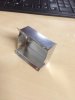
With the arm off, this is a good time to look at the bracket. This is the same style bracket I used for all of the dummy arms. This one has a large hole to accommodate the round area on the servo that surrounds the gear. The hole on the opposite side was enlarged to allow a screwdriver to slip through.
 
That's really cool to have the arm actually working!

On a different note ( pun intended ), are you using the sounds from the Yahoo Group?
Were you able to clean them up any? There seems to be some background noise in them.

Here's something I've been working on.

View attachment 274878
 
I do have the sounds from the Treadwell Builders Group on Yahoo. I haven't done anything with them except make a playlist. I think I will use some of similar cleaned up R2 and mouse droid sounds to help fill out my sound board. I do not know where to begin in terms of cleaning up a recorded sound. Any advice here would be great.

The wheel looks great, are you planning on having it machined or printed? I may at some future point revisit the wheels to make them more screen accurate.


Sent from my iPad using Tapatalk
 
I haven't heard the yahoo group sounds and you're probably way ahead of me, but Treadwell sounds can be had from the radio drama, and from Obi-Wan's fighter's astromech in the opening of Ep III. And on top of the Falcon in ESB, of course. In addition to the brazzy beeps, there are hissing-like sounds that can be faintly heard as one passes by in the background when Luke's looking for Artoo with the macros in ANH. None of these sources are particularly clean, though.
 
Thanks Treadwell! I didn't realize that Obi-Wan's astromech made those sounds. I figured I would go through the films and see what I can pull off. There are only a handful on the Yahoo group. Once I collect the sounds, I am not too sure how I will clean them up.
 
Ultimately I would like to have them machined. I'm wondering how strong they would be if printed in the steel material. Also need to find out if the material can be tapped for threads. The wheel design is part of a 3 piece system that bolts together.

As far as the sounds, I'm not sure on how to clean them up either. Have to do some research on that.
 
Another quick update, I didn't have much time at home this week. But I did get the gripper arm weathered and reattached. Here are a couple of pictures. The next task will be to get all the wires running down through the body.

2014-01-18 13.19.30.jpg 2014-01-18 13.29.59.jpg 2014-01-18 13.30.11.jpg
 
Before I could really deal with the wires, I wanted to get the neck mechanism in place.

I am using standard servo in ServoCity's new servo bracket. I will attach a shaft that will be connected to the new neck piece.
2014-01-24 17.37.01.jpg

To get this to work, I cut a sizable notch into the top of the body.
2014-01-24 17.36.33.jpg

The whole bracket is held into place with screws.
2014-01-24 17.38.24.jpg

The bracket will be covered with bottom portion of the neck piece. Also the servo sticking out of the side of the body will be covered with a small metal box. Treadwell had a couple of these along the body that the pneumatics and wires were passed through.
 
Adding three small metal boxes along the body to help with wire management and to conceal the neck servo.

2014-01-24 23.41.10.jpg 2014-01-25 00.04.07.jpg 2014-01-25 00.47.59.jpg

The boxes where all made the same way. I used a sheet of aluminum and cut and shaped it into the box.

2014-01-24 23.48.52.jpg 2014-01-24 23.56.34.jpg


I drilled holes into the body where the wires will slip down to the base. I am having troubles uploading pictures at the moment, so I will try again shortly.
 

Attachments

  • 2014-01-25 00.04.27.jpg
    2014-01-25 00.04.27.jpg
    2 MB · Views: 131
Drilled holes into the body to allow the servo wires to pass down to the base.
2014-01-24 17.43.13.jpg

The boxes were attached over the holes and I used one to cover the neck servo.
2014-01-25 00.25.30.jpg 2014-01-25 01.07.05.jpg
 
Last edited:
Started the neck by first drilling out the 1/2 inch holes for the head pivot. And inserted a 6 inch steel rod.
2014-01-08 21.40.12.jpg

Back on page two of this log I marked out the placement of the servo and the areas needing to be trimmed. Here the neck has been trimmed and sanded.
2014-02-03 16.21.12.jpg

I wanted to make sure everything looks right and has enough space. So I assembled everything to see how the neck looks attached to the body.
2014-01-25 00.29.32.jpg 2014-01-25 00.25.53.jpg 2014-01-25 01.09.18.jpg 2014-01-25 00.30.01.jpg
 
Today I am prepping the neck. I have sanded and primed it a couple of times and I am still deciding whether or not I will be molding it. I also wanted to make sure everything fits properly.

So first, I sanded and primed the base of the neck and then gave it a coat of aluminum colored spray paint.
2014-02-05 14.49.10.jpg


Then I fabricated the aluminum strip that will connect the neck to the head. I measured the space on the neck and on the head. Then transferred everything to the aluminum strip. Drilled out the 1/2 inch holes and then bent into shape.
2014-02-05 14.02.26.jpg 2014-02-05 14.02.59.jpg 2014-02-05 14.03.26.jpg
 
Here are all of the parts that be assembled for the head and neck.
2014-02-05 14.04.33.jpg

Assembled the aluminum strip to the neck to make sure the holes ended up balanced.
2014-02-05 14.22.23.jpg

Again, measured the head to make sure the aluminum strip is centered on the head and attached it with small screws.
2014-02-05 14.28.25.jpg 2014-02-05 14.46.24.jpg 2014-02-05 14.48.09.jpg


The head attached to the neck for the first time.
2014-02-05 14.58.22.jpg 2014-02-05 14.59.02.jpg
 
Thanks Batbassi!

I am going to use a servo to move the head up and down. However there is a lot of weight for the servo to move around. I will be using a expansion spring to counter the weight just like in the original build.

2014-02-05 17.20.32.jpg Drilled a small hole in the back of the eye to mount the spring.


2014-02-05 17.21.20.jpg Used a small screw and washer to attach the spring.

2014-02-08 11.55.20.jpg Drilled another small hole through the base for a 4-40 screw and nut.

2014-02-08 11.58.25.jpg Attached the spring.

2014-02-08 11.59.52.jpg The head is now perfectly balanced with the spring attached. The servo can now easily lift up and pull down on the front side of the pivot point.
 
Now adding the mechanism to get the eyes to look up and down.

Here is the servo with the linkage attached. Also, I screwed on the servo blocks from Servo City to mount directly to the neck.
2014-02-08 15.46.37 HDR.jpg

Made two marks where the servo blocks meet the neck and drilled two holes for a pair of 4-40 screws.

2014-02-08 15.48.45 HDR.jpg 2014-02-08 16.19.01.jpg 2014-02-08 16.20.23.jpg


The bent end of the linkage slips loosely into a hole in the bottom of the brass tube that connects the two eye pieces together.
2014-02-08 16.22.01.jpg

Here is a quick video of how the servo works.

 
Last edited by a moderator:

Your message may be considered spam for the following reasons:

If you wish to reply despite these issues, check the box below before replying.
Be aware that malicious compliance may result in more severe penalties.
Back
Top