Alright so that tear-down video that FANATICO posted had enough information to not only confirm a way to give my tricorder video playback, but also showed me how to control the video with my phaser and hear the playback on my communicator. All accomplished with a raspberry pi and some accessories. I don't know if anyone cares to hear my plan, but too bad here it comes:
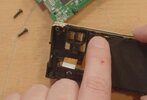
The video clearly shows the LCD screen connects to the main circuit board via a 24 pin ribbon cable:
View attachment 1954651
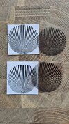
If there is enough room for it, I can connect that cable to a 24 pin extender:
View attachment 1954652
And then run a second ribbon cable down to the lower compartment of the tricorder and connect it to a display adapter board:
View attachment 1954653
Which will connect to the pi:
View attachment 1954654
If I'm right this is all I need to make the tricorder screen a display for the raspberry pi, and adding a small flash drive to the pi will give me the ability to load up some episodes and watch them on my tricorder screen.
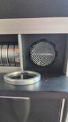
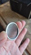
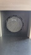
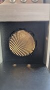
Now for the phaser remote. Also visible in the tear-down video is the back of the "sensor array", and like he says in the video, "In case you're wondering, behind this mesh screen... there is nothing."
View attachment 1954656
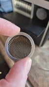
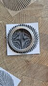
And a closer look at mine shows the screen is perforated, and should therefore allow the signal from an IR sensor to get through:
View attachment 1954657
So now I can add an IR sensor behind it:
View attachment 1954658
And then a bluetooth module for the sound output to the communicator:
View attachment 1954659
And finally a power supply for the raspberry pi:
View attachment 1954660
Obviously, if I do this, I will lose access to the original tricorder operating system and all its functionality, possibly including the lights from the 3 buttons and the moire lights and movement. This is the trade-off.
Also will it all fit? probably not.
This is just an unhinged, late-night idea I've concocted after finally seeing the inside of the "Activities Unit"
Will I do it? Probably yes. And right after I'm done someone will release a jailbreak for the tricorder OS and mine will officially be the dumbest way to get video playback on the trike screen.