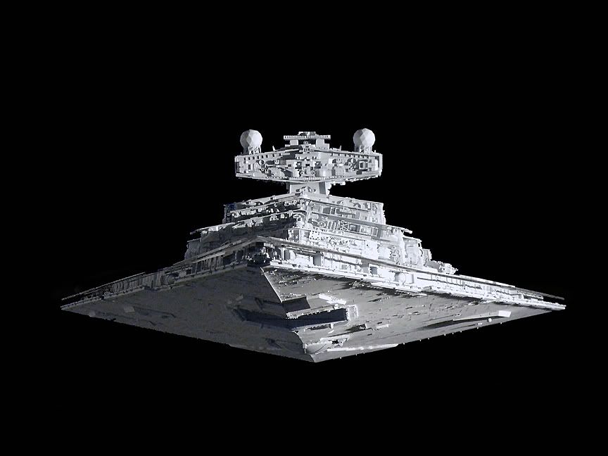
This segment may read like a tutorial in a way, but I've learned some valuable things while building Star Destroyers that may be of use to those who want to take a crack at it for themselves.
There are four things I'll be covering this time; Domes, Panel Scribing, the importance of being able to attach and detach the hull, and finally, Nose Detail.
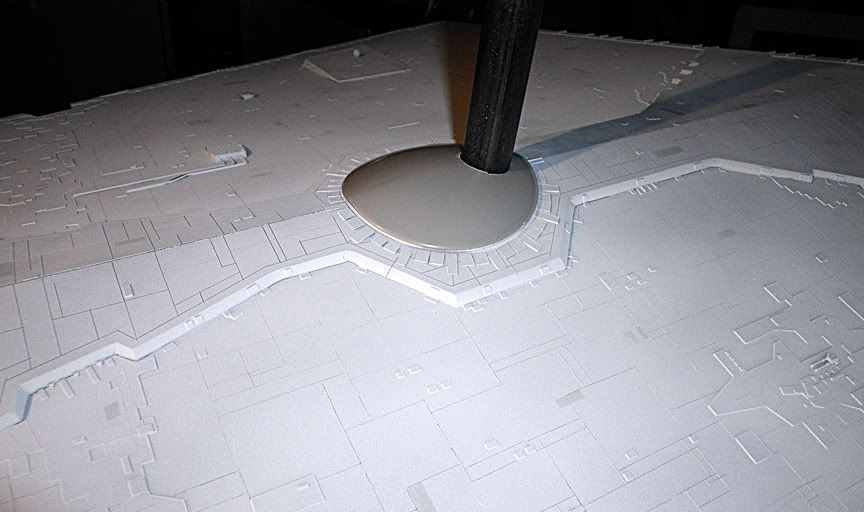
First the dome. As I wait for the domes I ordered to arrive I received the AMT 1/25 Frauhauf Tanker kit. I was going to use the dome from this kit before I found out from Lorne Peterson how this part of the filming model was actually made. As an experiment, I decided to prepare the part as though I were going to use it.
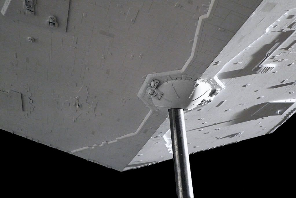
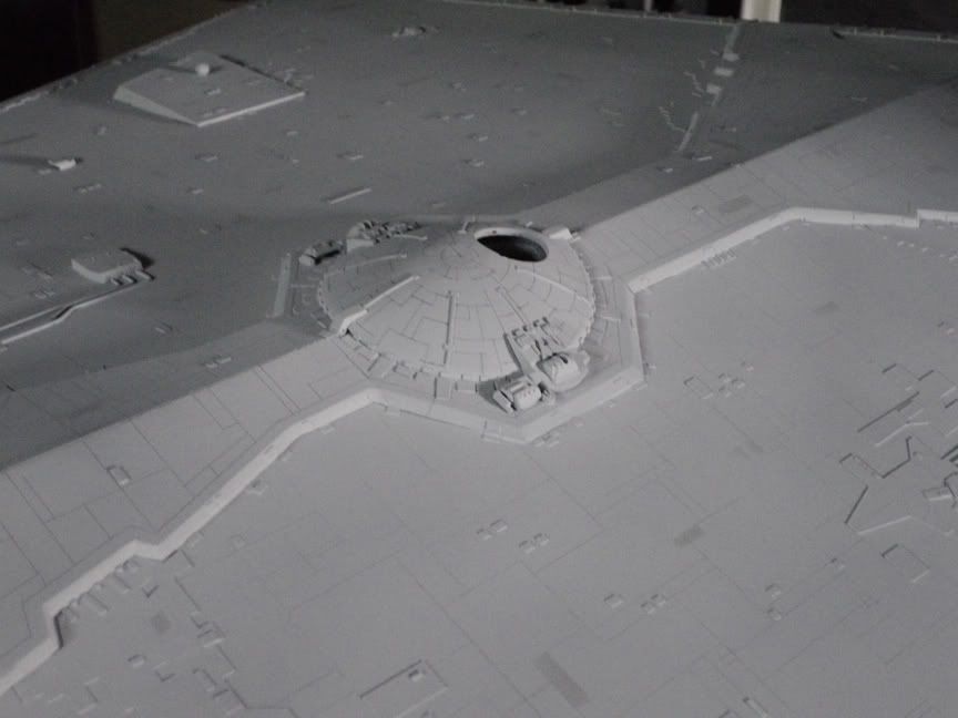
The problem is how to make a flat dome fit over the angled hull. On the original, a dish dome was used as a buck for vacuuforming thin styrene over it. It was then bent over the hull and trimmed. However, the tanker kit dome I found is too small in diameter by about a quarter inch. if it were to be used, the trimming technique would only make it even smaller. So I tried a technique that would preserve its size while still fitting it over the hull. By waving it back and forth over a lit candle (not getting too close as to melt the part to deformity), the heated plastic softens just enough to make it pliable down the middle. I then draped it over the hull and held it there until the dome's new shape became permanent as it cooled. I then drilled a hole in it where the mounting bar goes through it. The dome now fits over the hull like it was made for it...
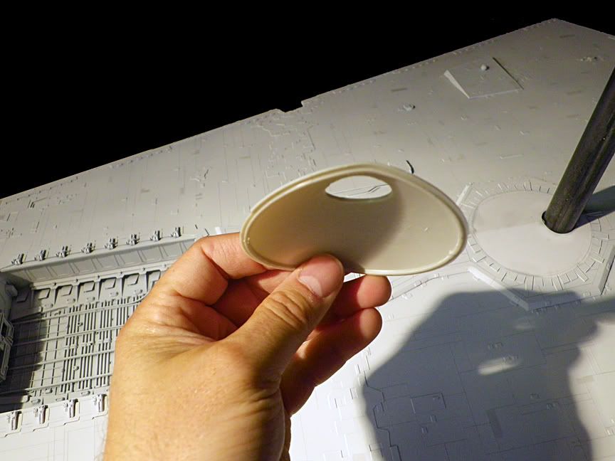
If you were to use this part, when the greeblies and panel lines are put on it they could disguise the fact that it is too small just enough to get by. Now, I bought enough of the correct size domes to try this technique on one of them, since it worked so well with this one. A good alternative if you don't have a vacuuformer.
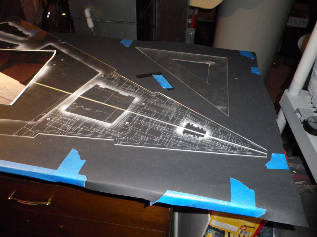
On to panel lines. I've learned that it is best to scribe the plexi hull panels before they are attached to the frame, and before anything is attached to the panels. This way you can lay them flat on a table without obstacles to work around. However, in doing it this way you create a problem because the structures that the panel lines interact with or wrap around are not there. How do you overcome this? Simple.
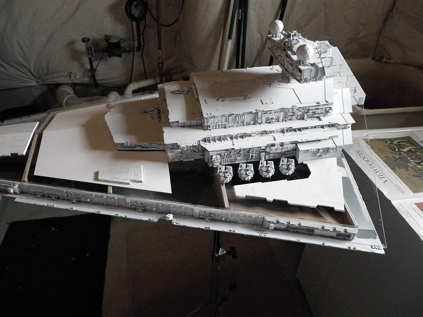
Prepare the plexi panels by first screwing them to the frame, then arranging all the structures where they belong. I made sure to measure their placement so they will be exactly where I want them when I am ready to attach them permanently...
Once I had all the pieces in place on the top hull, I then lightly airbrushed a mist of white paint around the edges of the pieces leaving an outline of where they will all eventually end up...
You might ask why not just trace around them with a pencil or hobby knife? Well, the most obvious reasons are because this way I have no chance of accidentally moving them out of position, marking them or damaging them. They are white already, so a mist of white doesn't hurt or move them. Now I have the areas defined where panel lines should go, and areas that can be masked where structures can be attached after the hull is painted.
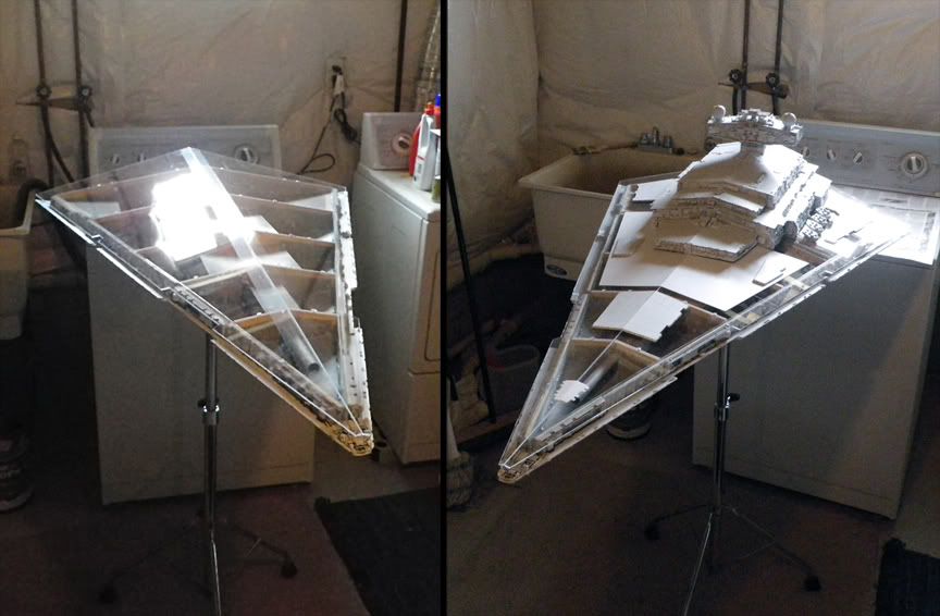
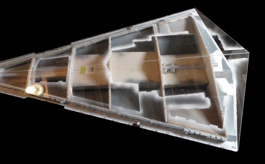
Because this model is entirely hand made like the original, I should mention here that there are valuable advantages to screwing the hull to the frame, then having the ability to remove them and reattach them several times while working on this model. In the process of doing this you can constantly tweak the frames so that the panels fit their best when you are ready to attach them for good. Every time I screwed them to the frame, it seems, I would find a different area that could be improved. I was also saved from a major disaster by doing it this way. When I first drilled the screw holes on the top hull, I must have moved the hull slightly so that all the holes were off by one millimeter to the port side. That may not sound like much, but a single millimeter threw the entire hull off enough so that the starboard side trench would have been much wider than the port side. VERY noticeable in a finished model, the "kiss of death," as my good friend Charles puts it. Because I am constantly attaching, detaching, reattaching the hulls, I was able to discover and correct the problem before it was permanent. I abandoned the original screw holes for corrected ones.
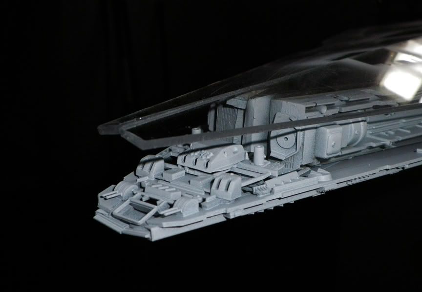
Now for the nose. I mention this because on the original filming model the nose was very detailed. At some point in its existence those parts were either removed or have fallen off. There is only one photo I know of (in the Chronicles) that shows the nose with a lot of detail. Since this photo is taken from below, it is very difficult to ID any parts in there. I want my model to have details in the nose, so I did what I always do when I have little reference... I made it up. Here are the details I added to the bottom hull. They will eventually be "sandwiched" by the pieces I have lined up to go on the top hull.
In Star Wars you always see laser bolts shooting from two areas in the nose. Maybe the original filming model had small guns in there, I don't know, but mine definitely does. I also studied many photos of the Avenger nose, which is well documented, to get ideas on how to do mine, yet without going overboard with too much detail.
So, at this point I have a top hull that is ready for scribing, a bottom hull that is ready for the correct dome to come in the mail, detailing the nose is covered (literally), and I have all the areas marked for the top structures when it is time to attach them permanently. When these things are done I can finally move on to the engines.
Hope you all enjoyed this, and I hope my experiences can help your projects in some way.
") Maybe I dont have the correct tool for styrene though...
Maybe I dont have the correct tool for styrene though...